Yaskawa DS391 User Manual
Page 5
DWG. NO. 02Y00025-0297
SHEET NO. 5 OF 7
REL. 01/30/91
( m - d f )
Refer to Sheet 1 for latest change.
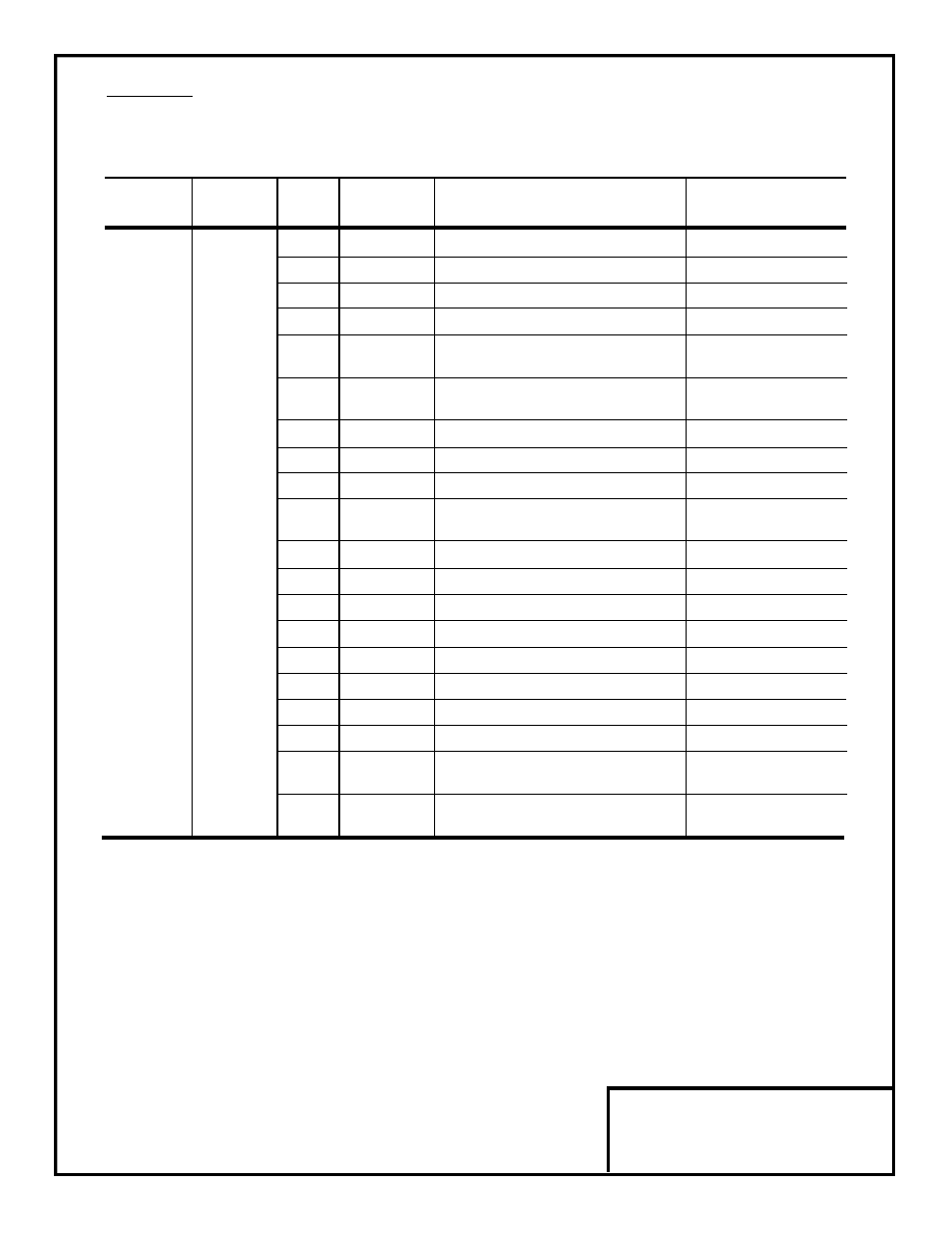
7. Adjustments. There are no adjustments to be made on the Analog Monitor option; however, the drive must be
reprogrammed for the output requirements of the peripheral devices. See Tables 4 – 6.
Table 4. Selecting Monitored Output (GPD 515)
Program
Set
Control
Terminal Parameter
Value
Method *
Output Monitored
Output
1
0, 1, 2, 3
Frequency Reference
10V/100%
2
0, 1, 2, 3
Output Frequency
10V/100%
3
0, 1, 2, 3
Output Current
10V/drive rated current
5
1, 2, 3
Motor Speed
10V/100%
6
0, 1, 2, 3
Output Voltage
10V/200V or
10V/400V
7
0, 1, 2, 3
DC Bus Voltage
10V/400V or
10V/800V
8
0, 1, 2, 3
Output power (kW)
10V/100%
TD1
F4-01
9
2, 3
Torque Reference (internal)
10V/100%
or
or
15
0, 1, 2, 3
Terminal 13 Input Voltage
10V/10V
TD2
F4-03
16
0, 1, 2, 3
Terminal 14 Input Voltage
10V/10V or
or Current
10V/20mA
17
0, 1, 2, 3
Terminal 16 Input Voltage
10V/10V
18
0, 1, 2, 3
Motor Secondary Current (Iq)
10V/motor rated current
19
2, 3
Motor Exciting Current
10V/motor rated current
20
0, 1, 2, 3
Output Frequency After Soft-Start
10V/100%
21
1, 3
Automatic Speed Regulator Input
10V/100%
22
1, 3
Automatic Speed Regultaor Output
10V/motor rated current
23
1, 3
Speed Deviation Regulator Output
10V/100%
24
0, 1, 2, 3
PID Feedback Amount
10V/100%
26
2, 3
Output Voltage Reference Vq
10V/230V or
10V/460V
27
2, 3
Output Voltage Reference Vd
10V/230V or
10V/460V
* Output available only when using one of the listed control methods
( A1-02 setting)
0 : V/Hz mode
1 : V/Hz mode with pulse generator (speed feedback)
2 : Open Loop Flux Vector
3 : Flux Vector