Yaskawa DS391 User Manual
Page 7
DWG. NO. 02Y00025-0297
SHEET NO. 7 OF 7
REL. 01/30/91
( m - d f )
Refer to Sheet 1 for latest change.
8. Reinstall and secure drive cover.
9. Place this instruction sheet with the drive technical manual.
THIS COMPLETES INSTALLATION OF THIS OPTION.
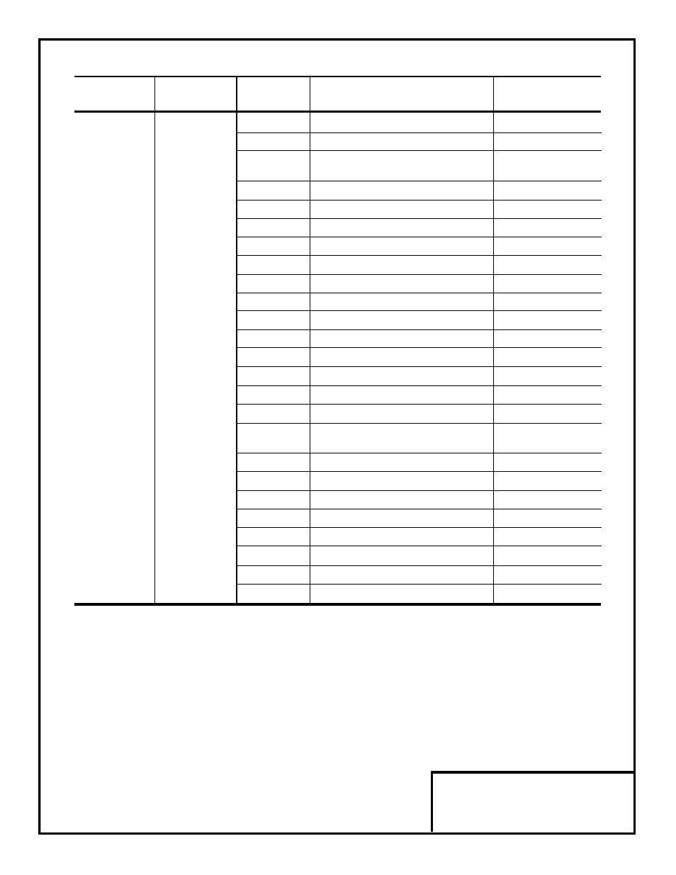
Table 6. Selecting Monitored Output (VCD 703)
Program
Set
Terminal
Constant
Value
Output Monitored
Output
3
Output current
10V/CT rating
4
Output voltage
10V/dn-04
5
DC Bus voltage (Vpn)
10V/200V (230V rated)
10V/400V (460V rated)
21
Speed reference (SFS input)
10V/100%
22
Speed reference (SFS output)
10V/100%
23
Speed feedback (Nfb)
10V/100%
24 *
External torque reference
10V/100%
25
Torque compensation
10V/100%
26
Torque reference
10V/100%
27 **
Torque feedback
10V/100%
TD1
bn-22
28
ASR input (speed deviation)
10V/100%
or
or
29
ASR output (after filter)
10V/100%
TD2
bn-24
30
Slip frequency reference
10V/100%
31
Primary frequency reference
10V/100%
32
Motor temperature
10V/200°C
33
Zero servo moving pulse count
10V/32767
34
Auto speed reference voltage
10V/10V
(terminal 13 or 14)
35
Analog input voltage (terminal 16)
10V/10V
36
AI-14B input voltage (CH1)
10V/10V
37
AI-14B input voltage (CH2)
10V/10V
38
AI-14B input voltage (CH3)
10V/10V
39
Magnetic flux feedback (phase
α
)
10V/100%
40
Magnetic flux feedback (pahse
β
)
10V/100%
41
ACR compensation
10V/100%
44
Output power (kW)
10V/100%
* When in Torque Control mode.
** When TRQ-A card is used.