Yaskawa MP2000iec User Manual
Page 4
Subject: Example Code Manual
Product: MP2000iec
Doc#: EM.MCD.09.095
Title: Example Code Manual for Linear Flying Shear on MP2300Siec Sigma-5 Demo using camming
July 13, 2009
Page 4 of 21
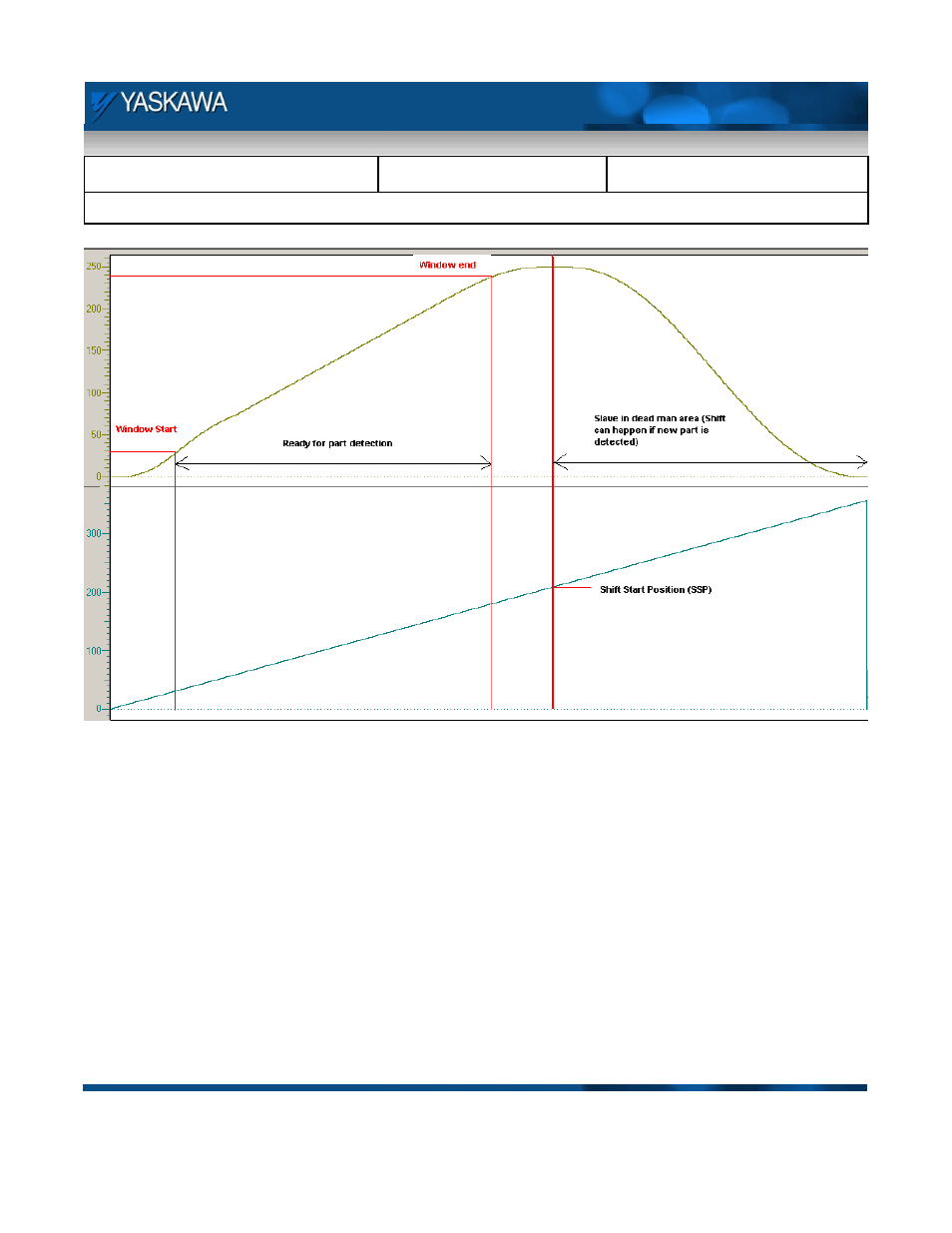
Figure 3: Critical positions on the cam master slave profile
Figure 3 details the critical points on the master and slave profiles. The algorithm followed to execute the linear
flying shear is shown in Figure 4. The algorithm starts with the shear axis (slave) at the home position and the
master axis running at a constant velocity. The slave axis waits for a registration mark from a part or on the
master axis. This triggers a shift in the master position such that the start of the cam cycle comes by when the
registration mark reaches the slave home position after covering the sensor to start distance (SSD). Once the
slave cams in and is synchronized, the window for capturing next registration latches opens up (when the slave
passes 30 mm of travel in the forward direction). If a registration is captured when the window for capture is
open, the position is stored and the calculation for phase and master distance is performed. The shift cannot
start immediately because when the shearing process is in progress, the slave and master need to be in tight
sync. Only after the shear is done, can the shift for the next part start. This is determined using a dead man area
on the slave’s position profile (user defined).