Yaskawa MP2000iec User Manual
Page 6
Subject: Example Code Manual
Product: MP2000iec
Doc#: EM.MCD.09.095
Title: Example Code Manual for Linear Flying Shear on MP2300Siec Sigma-5 Demo using camming
July 13, 2009
Page 6 of 21
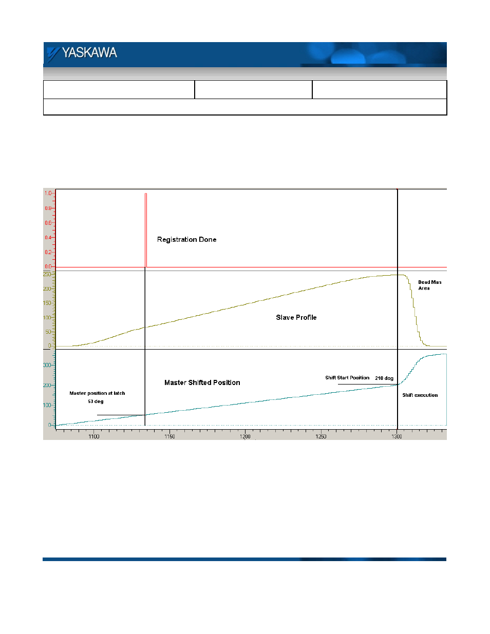
The phase is calculated by noting the difference in two consecutive latches on a 360 degree cycle. The master
distance is calculated as (SSD – (SSP – Master shifted position)) where SSD is distance the part has to travel to
get to the shear home position. SSP is the shift start position which is the position on the master from where the
shift can start. This is shown in Figure 5.
Figure 5: Implementation of cam shift
Figure 6 is an illustration of continuous part registration at unequal intervals. Shift one is executed for the first
latch (registration) seen in figure 6. Since the second registration was very early in a cycle, the shift to get the
slave back to home position is very large. This large shift over a small distance causes the slave to return back to
home in a very fast move on the return stroke as can be seen from shift 2. Since the third registration happens
almost at the end of the window, the phase shift is small and it has more distance over which to implement the
shift. It can be seen from Figure 6 that the third shift does not cause a major change in the cam profile.