Yaskawa F7 Drive Enhanced PID for Air Compressor User Manual
Page 12
Date: 08/01/05, Rev: 05-08
Page 12 of 17
TM.F7SW.096
5.2 Modified PID “Sleep” Function
In standard software, parameter B5-16 controls both the sleep delay, and the wake-up delay. In this
software, parameter B5-16 controls the sleep delay, and P2-06 controls the wake-up delay. The
maximum settable range of B5-16 is increased from 25.5 seconds to 600.0 seconds.
An additional timer has been added (P2-07) to the sleep function to insure that when the drive does go
into the sleep mode, it remains in sleep mode even if the PID is calling for the drive to run. This is to
insure that the pressure in the “sump” of the air compressor can dissipate before it restarts. This
prevents foaming of the oil.
5.3 Blowdown Valve Digital Output
This digital output can be used to control the blowdown or loading valve for the air compressor. When
this output is energized, the blowdown valve is active, and the compressor is allowed to make air. If this
output is de-energized, the air compressor won’t produce any air, even if it is turning. This output should
normally be energized when the drive is running, but only after a delay after startup (determined by
parameter number P2-08). This allows the motor, drive, and compressor to start under less load. The
output will also de-energize if the PID feedback (air pressure) goes too high. The level, time delays, and
hysteresis share the same parameters as the PID feedback high detection alarm and fault. (P1-02, P1-
03, P1-04, and P1-08). See Section 6.5 for a detailed block diagram.
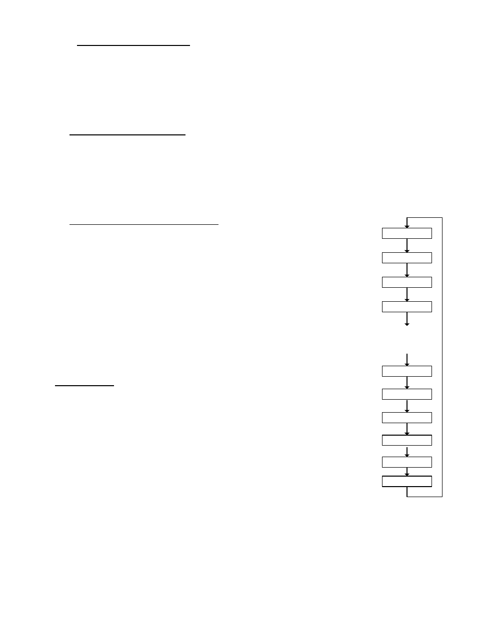
5.4 Customized Display of Keypad Monitors
When first powered up (or returning to the drive mode), the digital operator display will
show pressure setpoint (U1-01), pressure feedback (U1-90), and output frequency
(U1-02). All PID setpoints (U1-01, D1-XX) and PID monitors (U1-9X) have user
selectable scaling (O1-03) and keypad display units (P2-09). User selectable units will
only be displayed when O1-03 ≥ 40 (custom units). Unit selections are PSI, kPa, and
o
F.
Other parameters that are normally scaled using O1-03, which include U1-02, U1-05,
U1-20, and U1-46, are scaled by parameter P2-10. Parameter P2-10 will work in
exactly the same manner as O1-03 does. When the setting is 0, the units and scaling
will be in 0.01Hz. When the setting is 1, the units and scaling will be in 0.01%. When
the setting is 2 ~ 38, the scaling will be in RPM, with the setting of P2-10 acting as the
number of motor poles for the calculation. When the P2-10 ≥ 40 (custom scaling), the
keypad display units are determined by parameter P2-09. Unit selections are PSI,
kPa, and
o
F.
6.0 Block Diagrams
The following pages give detailed flowcharts of the following software functions:
6.1 PID with 2 Inputs (B5-01 = 1 or 2)
6.2 PID with 2 Inputs (B5-01 = 3 or 4)
6.3 PID with 3 Inputs (B5-01 = 3 or 4)
6.4 PID Feedback Detection
6.5 PID Sleep function and Blowdown Valve Digital Output
U1-01
U1-90
U1-02
U1-03
U1-94
U1-96
.
.
.
U1-93
U1-92
U1-91
U1-95