Yaskawa F7 Drive Output Voltage PID User Manual
Page 2
Date: 05/05/05, Rev: 05-05
Page 2 of 8
TM.F7SW.061
This document is intended to provide proper installation and use of the Yaskawa drive with custom software. This
document is a supplement to the standard drive technical manual. It describes the effects on the drive parameters
and functions with the software installed. Read and understand this document and the standard drive technical
manuals before attempting to install, adjust, operate, inspect or maintain the drive. Observe all cautions and
warnings in this document and the standard drive technical manuals. Custom software is written to add
functionality to a standard AC drive to enhance or enable use in a specific application. The software is loaded to
the flash ROM area of the control board, and replaces the standard drive software. Custom software can add new
functions, modify standard functions, or even inhibit standard functions. It can be used to modify display text or
parameter names. Custom software is usually loaded to the drive before delivery. The control board and drive
nameplate are assigned unique part numbers and the software is registered, archived, and retrievable.
When seeking support for a drive with custom software, it is imperative to provide the unique part number shown
on the drive nameplate. The software has been flashed to the control board memory and the operation of
parameters, functions, and monitors are different than the standard drive software, as described herein.
1.0 Overview
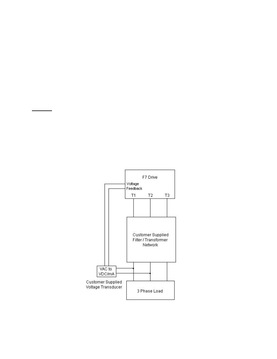
This Output Voltage PID software allows an F7 drive to control its output voltage independent of its frequency.
The software was created for the following applications: Uninterruptible Power Supply (UPS), Marine Power
Supply, Medical Power Supply (CT and MRI), and Vibratory Welder.
An independent PID controller is added, the output of which will trim the output voltage. This is useful for
regulating the voltage on the output side of a sinusoidal filter. The trim range for the PID controller is +13% to -
100%. Two additional dynamic compensation functions are also added for RMS current (Iac) and secondary
current (Iq).
Application Example of Output Voltage PID