Yaskawa F7 Drive Output Voltage PID User Manual
Page 6
Date: 05/05/05, Rev: 05-05
Page 6 of 8
TM.F7SW.061
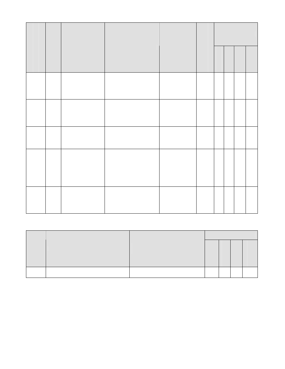
5.2 Monitors (U1-XX)
Control Mode *1
Monitor Num
ber
Modbu
s Add
ress
Monitor Name
Digital Operator
Display
Description
Scaling for
Multi-function
Analog Output
Terminals
FM and AM
(H4-01, H4-04)
Unit
V/f
V/f w/ P
G
Open Lo
op
Vector
Flu
x
Vector
U1-90 720h
Voltage Feedback
Voltage
Feedback
Displays the analog
input feedback sensor
voltage.
Note: Scaled by P1-07.
N/A
0.1
VAC
A - - -
U1-91 721h
Voltage Error
Voltage Error
Displays the difference
between the voltage
setpoint (P1-01) and
the analog input voltage
feedback.
100% =
100VAC
0.1
VAC
A - - -
U1-92 722h
Output Voltage
PID Output
Voltage PID Out
Displays the
contribution of the
output voltage PID
controller.
100% =
100VAC
0.1
VAC
A - - -
U1-93 723h
RMS Output
Current
Compensation
Level
Iac Comp
Voltage
Displays the
contribution of the RMS
output current (Iac)
compensation function.
100% =
100VAC
0.1
VAC
A - - -
U1-94 724h
Iq Voltage
Compensation
Level
Iq Comp Voltage
Displays the
contribution of the
secondary current (Iq)
compensation function.
100% =
100VAC
0.1
VAC
A - - -
*1: Access Level (A1-01): Q = “Quick Start”, A = “Advanced”, F = “Factory”.
4.3 Multi-function Analog Input Settings (H3-05, H3-09)
Control Mode
Setting
Description
Scaling for 100% Input
(10VDC or 20mA)
V/f
V/f w/ P
G
Open Lo
op
Vector
F
lux Vector
20
Output Voltage PID Controller Voltage
Feedback Signal
100% = P1-07 Value
√ - - -
√: Available.