Control terminal sizes and wire sizes, Terminal comparisons, V1000 – Yaskawa VS606 V74X V7 to V1000 User Manual
Page 11: Awg) recommended wire size mm
PL.V1000-4X.01 Transition Guide 6/22/10
Page 11 of 32
Yaskawa America, Inc.
Product Transition Guide
PL. V1000-4X.01 Rev: 6/22/10
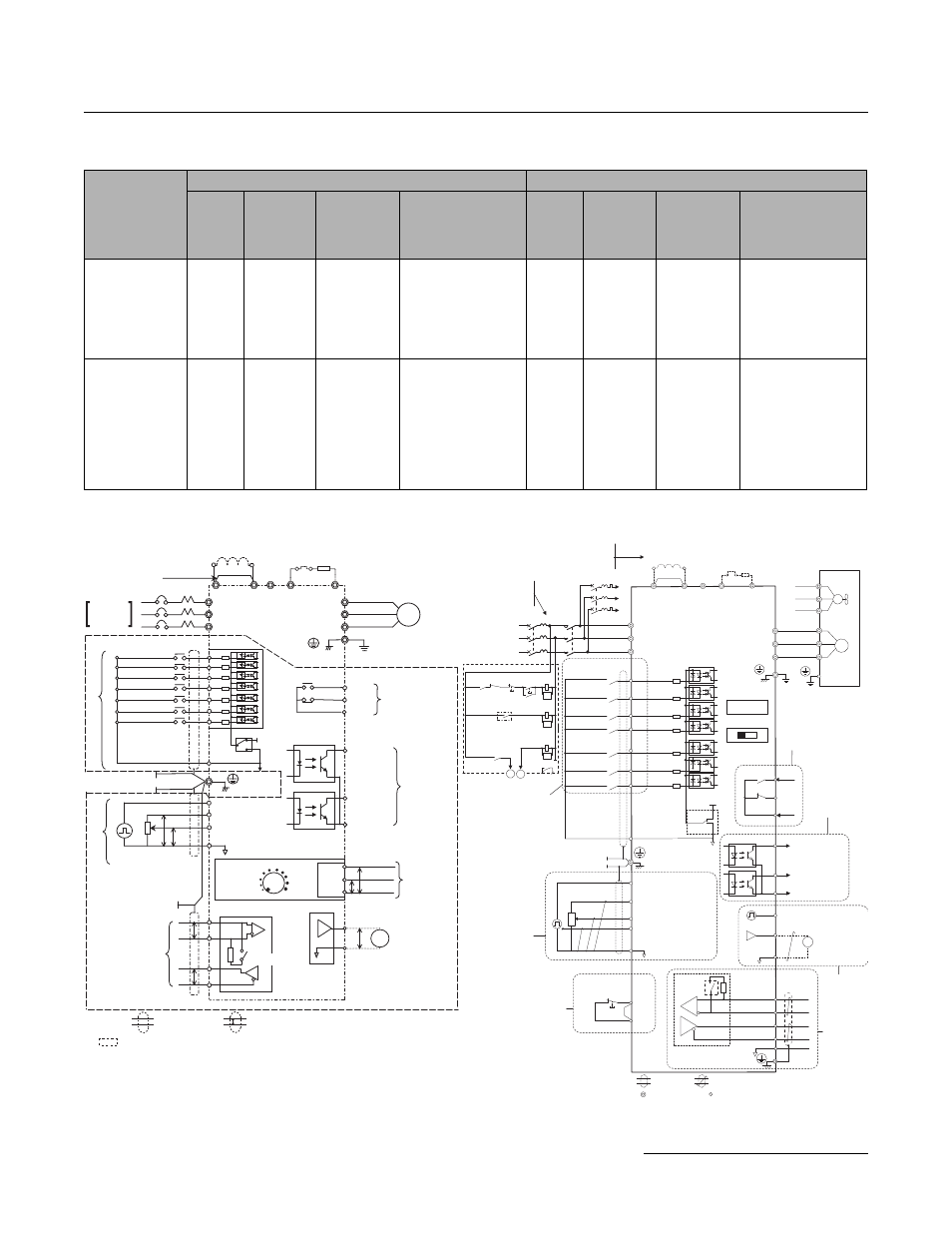
Control Terminal Sizes and Wire Sizes
Terminal Comparisons
Note: Refer to Installation & Start-Up Manual (TOBPC71060635) for warnings, cautions and additional notes.
Terminals
(New/Changed
in V1000-4X)
V74X
V1000-4X
Screw
Size
Tighten.
Torque
N•m
(in-lbs)
Applicable
Wire Size
mm
2
(AWG)
Recommended
Wire Size
mm
2
(AWG)
Screw
Size
Tighten.
Torque
N•m
(in-lbs)
Applicable
Wire Size
mm
2
(AWG)
Recommended
Wire Size
mm
2
(AWG)
MA, MB,
MC
M3
0.5~0.6
(4.4~5.3)
Stranded
0.5~1.25
(20~16)
Solid
0.5~1.25
(20~16)
0.75
(18)
M3
0.5~0.6
(4.4~5.3)
Stranded
0.25~1.25
(24~16)
Solid
0.25~1.25
(24~16)
0.75
(18)
S1-S7, P1, P2,
SC, PC, R+,
R-, S+, S-, FS
(V+) FR (A1),
(A2), FC (AC),
AM, AC, RP
(MP), (HC),
(H1)
M2
0.22~0.25
(1.9~2.2)
Stranded
0.5~0.75
(20~18)
Solid
0.5~1.25
(20~16)
0.75
(18)
M2
0.22~0.25
(1.9~2.2)
Stranded
0.25~0.75
(24~18)
Solid
0.25~1.25
(24~16)
0.75
(18)
V74X
V1000-4X
SA
Motor
Cooling fan
Forward run/stop
Reverse run/stop
External fault
Fault reset
Multi-step
speed 2
Jog reference
0 to +10 Vdc
(2 mA)
DIP
switch S3
DC Link Choke
(option)
Digital inputs
(default setting)
Comm.
connector
Safe Disable
Input
Safety switch
Fault
V1000
Shield ground
terminal
Thermal relay
(option)
Braking resistor
(option)
Main circuit
Control circuit
Thermal relay for
motor cooling fan
Fault relay
1 MCCB
MC
2 MCCB
r1
s1
t1
R/L1
S/L2
T/L3
S1
S2
S3
S4
S5
S6
S7
-
B1
+1
+2
B2
R/L1
S/L2
T/L3
MC
THRX
TRX
MC
TRX
MC MA
U/T1
V/T2
W/T3
24
V
0
V
MA
P1
MB
MC
V
I
+24
V 8
mA
M
M
r1
s1
t1
FU
FV
FW
U
V
W
SC
P2
MP
AM
AC
PC
IG
R+
R-
S+
S-
+
-
AM
HC
H1
RP
+V
A1
A2
AC
2 k
W
Pulse train input
(max. 32 kHz)
Ground
10
W or less (400 V class)
100
W or less (200 V class)
0 to +10 V (20 k
W)
Setting power supply
+10.5 max. 20 mA
0 to +10 V (20 k
W)
(0)4 to 20 mA (250
W)
For single phase 200 V
power supply, use
R/L1 and S/L2.
During Run
(photocoupler 1)
Frequency agree
(photocoupler 2)
Photocoupler
output common
Digital output
5 ~ 48 Vdc
2 to 50 mA
(default setting)
Pulse train output
0 to 32 kHz
Analog monitor
output
Digital output
250 Vac, 10 mA to 1 A
30 Vdc, 10 mA to 1 A
(default setting)
MEMOBUS/
Modbus comm
RS-485/422
Main speed
frequency
reference.
Multi-function
programmable
Multi-step
speed 1
main/aux switch
2 MCCB THRX OFF ON MC
SA
SA
Three phase
power supply
200 to 240 V
Jumper
DIP switch S1
Sink
Source
Termination
resistor
120
W, 1/2 W
Terminals +1, +2, , B1, and B2
are for connecting options.
Never connect power supply
lines to these terminals.
_
Monitor
output
Jumper
Option card
connector
DIP
switch
S2
main circuit terminal
shielded line
twisted-pair shielded line
control terminal
Cable shield ground
R
S
T
S1
+2
+1
B1
B2
-
S2
S3
S4
S5
S6
S7
SC
SW1 NPN
+24V
PNP
RP
FS
FR
P
P
2k
W
FC
R+
R-
S+
S-
MIN
MAX
FM
P
P
0 V
4 to 20 mA
0 to 10 V
P
GND
IIN
VIN
AM
PC
MC
MB
MA
W/T3
V/T2
U/T1
T/L3
S/L2
R/L1
U
X
P1
P2
1
2
3
AC
CN2
0V
Frequency Setting
Potentiometer
Reference Pulse Train
(Max. 33 kHz)
Frequency Reference
0 to +10 V (20 k
W)
4 to 20 mA (250
W)/0 to 20 mA (250 W)
Frequency Setting Power
Supply (+12 V 20 mA)
Digital Operator
Frequency
Setting
Potentiometer
IM
P
P
FORWARD RUN/STOP
REVERSE RUN/STOP
FAULT RESET
MULTI-STEP
SPEED REF. 1
MULTI-STEP
SPEED REF. 2
JOG
COMMAND
For Single-
phase.
Use R/L1
and S/L2.
Multi-function input
EXTERNAL FAULT
(NO CONTACT)
Power Supply
DC Link Choke
(Optional)
Thermal
Overload
Relay
Braking Resistor
(Optional)
Short-circuit bar*1
MCCB
Frequency Ref.
Pulse Train Input
MEMOBUS
Communications
RS-485/422
Max. 19.2 kbps
Grounding
Multi-function
Contact Output*2
250 VAC 1 A or less
30 VDC 1 A or less
FAULT
RUNNING
FREQUENCY
AGREED
Multi-function
Photocoupler
Output
+48 VDC 50 mA
or less
Analog Monitor
Output
0 to +10 VDC (2 mA)
Multi-function
analog input
Output
Frequency
Analog Monitor/Pulse
Monitor Selectable
Shield connection
terminal
Terminal Resistance
(1/2 W, 120
W)
Shielded twisted-pair cable
Shielded
: Only basic insulation (protective class 1, overvoltage category II) is provided for the
control circuit terminals. Additional insulation may be necessary in the end product to
conform to CE requirements.
*1. Short-circuit bar should be removed when connecting a DC reactor.
*2. Minimum permissible load: 5 VDC, 10 mA (as reference value)
P