Yaskawa Remote Display Controller LAN Node PCB for use with Microtrac DSD LAN User Manual
Page 3
INTRODUCTION
This document explains the
hardware and software operations of the
Remote Display Controller LAN Node PCB
(RDC).
The Remote Display Controller LAN
Node PCB (RDC) provides the MicroTrac
DSD system with the ability to have remote
displays with a minimal amount of wiring.
The RDC can support up to 31 Remote
Display Units (RDUs) through use of an
RS-485 bidirectional serial data bus (see
Table 1). Each RDU has a 16 character
alphanumeric display and a 5-1/2 digit
numeric display with a sign character. Any
one or all of the RDUs may have a keypad
or push buttons which will allow for
functions such as selecting a new message
to display or setting a numeric value.
The RDC communicates through use
of a Local Area Netwotk (LAN) using a
proprietary message protocol defined by
MagneTek. This protocol allows messages
to be sent to and from the RDC in order to
pass display and numeric information (e.g.,
Armature Current, Line Speed, etc.).
The RDC also allows a Portable
Control/Display Unit (PCDU - described in
the MicroTrac DSD Technical Mnaual) to be
plugged into a provided connector. The
PCDU allows the viewing of the source of
information to be displayed on each RDU.
Through use of the PCDU, the items
displayed on each RDU can be changed
from the default items. The PCDU also has
a test mode which has a limited function
Hex Monitor which may aid in trouble-
shooting a system.
The RDC uses a High Impedence
Transceiver (HIT) for signal transceiving in
order to utilize a bus topology on the LAN.
NOTE
For a full discussion of the LAN,
refer to the MicroTrac DSD
technical manual, TM 6100.
HARDWARE DESCRIPTION
POWER REQUIREMENTS
The power connector on the RDC is
used to supply the RDC with power. In
order to select a properly sized power
supply, the current (I) requirements of the
RDC for each of the voltages must be
known. The I requirements are as follows:
I for +5 VDC = 1300 mA
I for +15 VDC = 0 mA
I for -15 VDC = 270 mA
I for +24 VDC = 0 mA
LAN INTERCONNECT
There are 2 connections which must
be made connect the RDC to the LAN.
1. Faston tab J6 must be connected
to chassis ground. This is necessary in
order to provide a return path for the
snubber network of the LAN.
2. Connect J2, a BNC connector, to
the LAN coaxial cable. In order to meet LAN
requirements, type RG-62/U coaxial cable
must be used.
3
RD 790-20
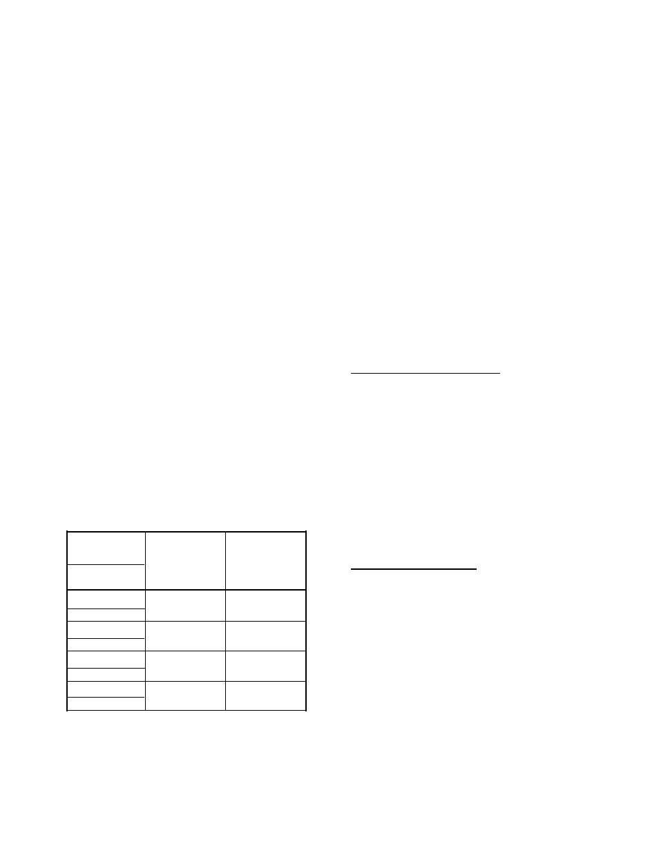
Table 1. RDC/RDU MAX MSGs
RDC
Maximum
Maximum
46S02970-
Number of
Number of
EPROM
*
RDUs
MSGs
97SA-
0020
31
12
0280-0004
0040
4
149
0380-0004
0050
10
54
0420-0004
0060
3
201
0800-0004
*
The principle difference between RDC PCBs is the
installed EPROM, which establishes the maximum
number of RDUs and MSGs.