4 inputs/outputs, 1 cn13 connection diagram – Yaskawa MP2600iec User Manual
Page 15
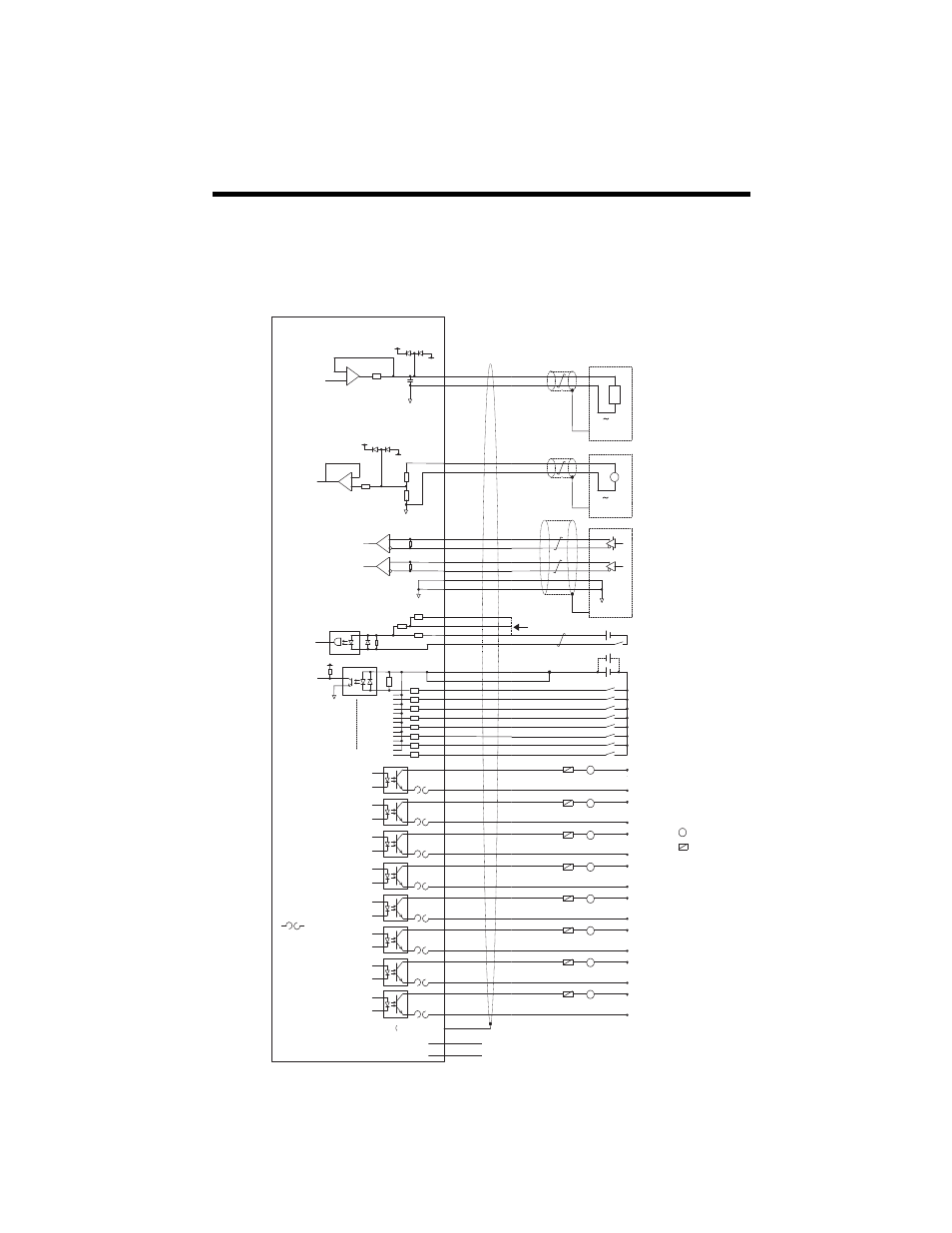
4.1 CN13 Connection Diagram
13
4 Inputs/Outputs
4.1 CN13 Connection Diagram
L
Load
NOTE: For a more detailed circuit drawing, see section 4.4.2.
* DO_07 can also be used as a high speed output when
configured via parameter 1050
External Fuse
(installed by
customer)
FG
1
L
External Device
-10
+10V
V
-10
+10V
FG
External Device
Pulse
Generator
FG
External Input
S
ignal
26
2
27
4
5
29
30
6
31
10
34
9
35
13
38
14
15
16
17
39
40
41
42
AO
AO_GND
AI
AI_GND
PA+
PA-
PB+
PB-
GND
GND
PILC(24V)
PILC(12V)
PILC(5V)
PIL
DICOM
DICOM
DI_00
DI_01
DI_02
DI_03
DI_04
DI_05
DI_06
DI_07
+
-
+15
V
-15V
+
-
+15
V
-15V
+5V
Analog
Output
Analog
Input
Encoder
Interface
Z-phase
Latch Input
Digital
Input
Digital
Output
Polyswitch Device:
A self-resetting
fuse if excessive
current is drawn
from the output
FG Connector Shell)
CN13
Latch Input
21
11
DO_00+
DO_00-
46
36
DO_01+
DO_01-
22
12
DO_02+
DO_02-
47
37
DO_03+
DO_03-
23
18
DO_04+
DO_04-
48
43
DO_05+
DO_05-
24
19
DO_06+
DO_06-
49
44
* DO_07+
* DO_07-
7
+ Battery
32
- Battery
Connect a positive voltage to pin 10, 34, or 9 based on signal level
L
+24VDC
0V
L
+24VDC
0V
L
+24VDC
0V
L
+24VDC
0V
L
+24VDC
0V
L
+24VDC
0V
L
+24VDC
0V
L
+24VDC
0V