Yaskawa Varispeed-686SS5 CIMR-SSA User Manual
Page 34
3
WIRING
35
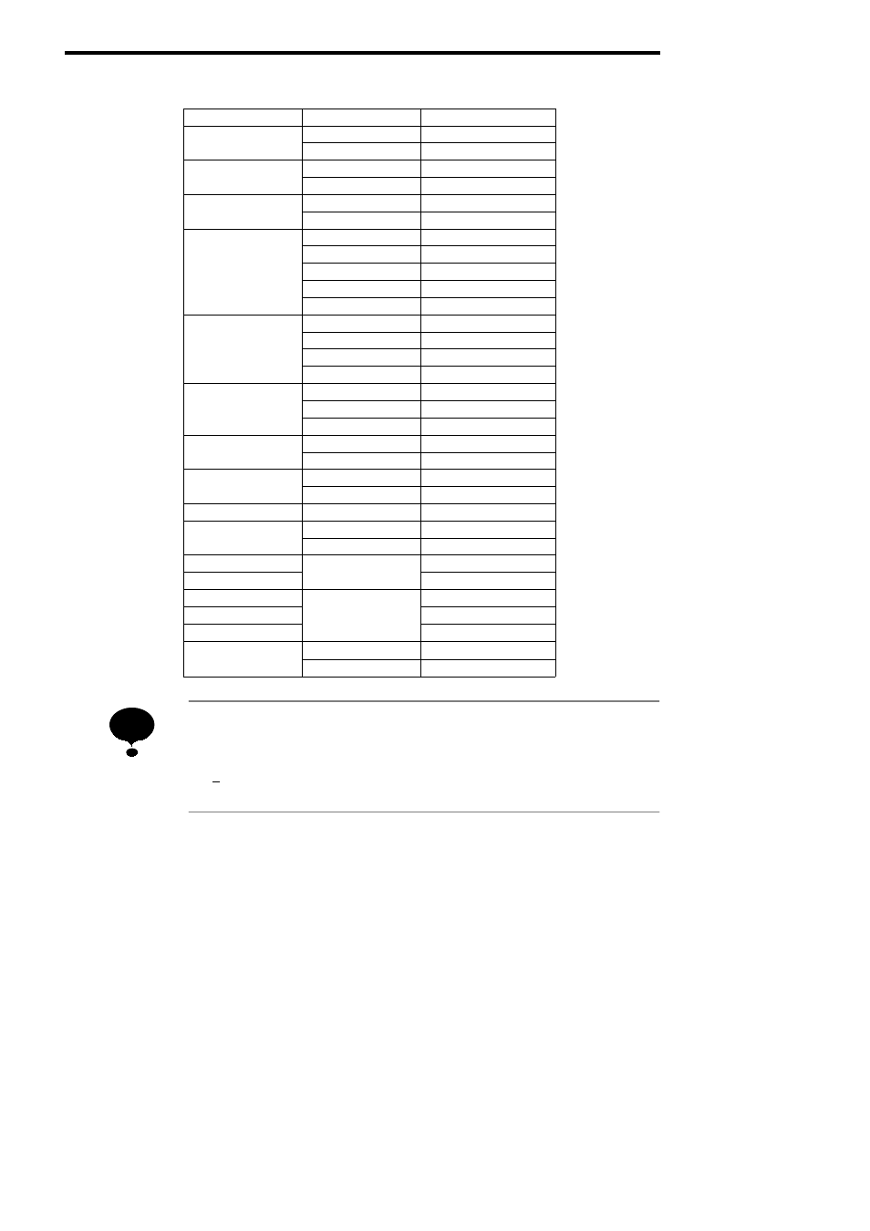
Table 7
Closed-Loop Connectors
Wire Size mm
2
Terminal Screw
Closed-Loop Connectors
0 5
M3.5
1.25 - 3.5
0.5
M4
1.25 - 4
0 75
M3.5
1.25 - 3.5
0.75
M4
1.25 - 4
1 25
M3.5
1.25 - 3.5
1.25
M4
1.25 - 4
M3.5
2 - 3.5
M4
2 - 4
2
M5
2 - 5
M6
2 - 6
M8
2 - 8
M4
5.5 - 4
3 5 / 5 5
M5
5.5 - 5
3.5 / 5.5
M6
5.5 - 6
M8
5.5 - 8
M5
8 - 5
8
M6
8 - 6
M8
8 - 8
14
M6
14 - 6
14
M8
14 - 8
22
M6
22 - 6
22
M8
22 - 8
30 / 38
M8
38 - 8
50 / 60
M8
60 - 8
50 / 60
M10
60 - 10
80
M10
80 - 10
100
M10
100 - 10
100
100 - 12
150
M12
150 - 12
200
200 - 12
325
M12 × 2
325 - 12
325
M16
325 - 16
When determining wire size, consider voltage drop. Select a wire size so that voltage drop will
be less than 2% of the normal rated voltage. Voltage drop is calculated by the following equa-
tion:
Phase-to-phase voltage drop (V)
=√ 3 ¢ wire resistance (Ω/km) ¢ wiring distance (m) ¢ current (A) ¢ 10
-3
NOTE