Appendix 6 rotation direction of motor – Yaskawa Varispeed-686SS5 CIMR-SSA User Manual
Page 91
92
APPENDIX 6 ROTATION DIRECTION OF MOTOR
If the standard connection is used for the output terminals of the main circuit, the motor rotates coun-
terclockwise as viewed from the load side of the motor in a forward operation.
To rotate the motor clockwise in a forward operation, use the following procedures to change the
connection of the terminals and the setting of the constants, check the motor speed detection, and
adjust the PG zero-pulse.
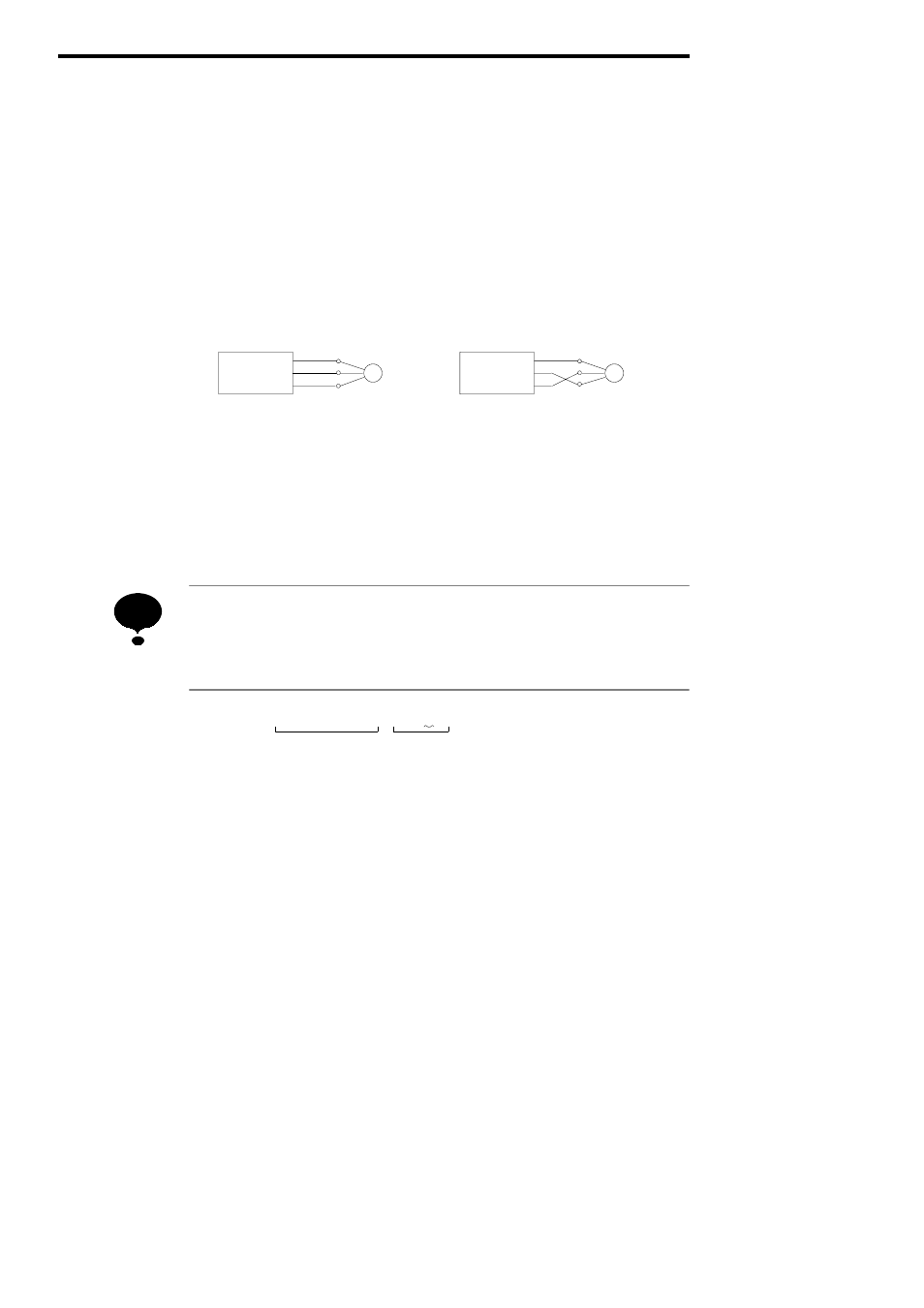
(1) Reconnect the output terminals of the main circuit:
Connect motor lead V to output terminal W.
Connect motor lead W to output terminal V.
Do not change the connection between lead U and output terminal U.
M
VS-686-SS5
U
V
W
U
V
W
M
VS-686-SS5
U
V
W
U
V
W
Standard Connection
Modified Connection
(2) Modify the setting of constant F1-05 (For flux vector control with PG)
Set F1-05 (PG rotation direction) to 0.
(3) Check the motor speed detection (For flux vector control with PG)
Refer to page 48.
(4) Adjust the PG zero-pulse (For flux vector control with PG)
Refer to page 49.
•
Do not change the connection of the PG cable.
•
If the rotation direction of the motor is set to clockwise for a forward operation (Refer
to Fig.A-2), change the connection of the output terminal of the main circuit to the
standard connection and then proceed to steps (2) through (4).
Basic Model
SSR1 − 20P4AEN − SAD1BES
Optional Model
Example)
The wavy lined code A: Counterclockwise rotation for forward operation (standard)
The wavy lined code B: Clockwise rotation for forward operation
Note: This example applies to optional model.
Fig. A-2Rotation Direction for Motor Model
NOTE