5 installation procedure, Figure 7 – Yaskawa V1000 Option - DI-100 120 Vac Interface User Manual
Page 17
5 Installation Procedure
YASKAWA ELECTRIC TOEP YEAOPT 03 - V1000 Option DI-100 120 Vac Interface Installation Manual
17
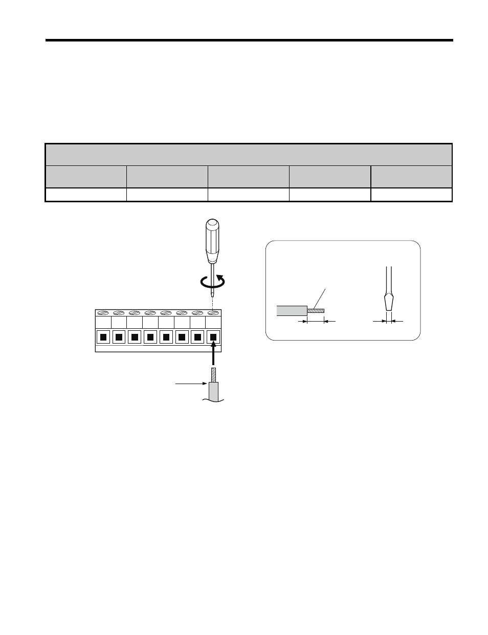
7. Prepare external 120 Vac control circuit wires (customer wiring) for terminals S1 ~ S7, X2
on the DI-100 option. Prepare the wire ends using
NOTICE: Wires to the option should be stripped according to
for maximum system safety. Use of
ferrules on the wire ends are recommended.
Table 4 Terminal and Wire Specifications
Figure 7
Figure 7 DI-100 Terminal Wiring Guide
8. Connect the prepared customer wiring to the DI-100 terminal block as shown in
for tightening torque.
is an example of a wiring
diagram showing customer interface circuitry.
Terminal and Wire Specifications
DI-100 Option
Terminal Symbols
Terminal Screw
Tightening Torque
(in-lbs)
Control Wiring
(AWG)
Recommended
(AWG)
S1 ~ S7, X2
M2
1.9 to 2.2
26 to 16
18 / 16
A – DI-100 terminal block
D – Loosen screw to insert wire.
B – Avoid fraying wire strands
when stripping insulation from
wire. Strip length 5.08 mm (0.2
in) ±20%
E – Blade depth:
0.4 mm (.0157 in) or less
Blade width:
2.5 mm (.089 in) or less
C – Single wire or stranded wire
Preparing
wire ends
E
A
B
D
C
X2 S1 S2 S3 S4 S5 S6 S7