Yaskawa iQpump Micro AC Drive User Manual
Page 1 of 4, Page 1 of 12
Step
1
Model Identification and
Mounting
Connect Motor and
Line Power
Step
2
Step
3
Page 1 of 4
WARNING! Fire Hazard. Only connect ground wiring to
designated ground terminals. Do not connect the following
terminals to earth ground.
9. Figures 1 and 2
show the electrical connections for input
power and motor terminals.
Select the proper figure for the
model being installed
(Refer to Step 1).
WITH POWER OFF make the appropriate connections.
Follow good wiring practices and all applicable electric codes.
Ensure the equipment is grounded properly
as shown in Figure 1.
W
WARNING! Hazardous Voltage. After the power is
OFF, wait at least five minutes until the charge indicator
extinguishes completely before touching any wiring, circuit
boards or components.
Verify the drive is properly sized for single phase input power. The drive
input supply voltage must be equal to or greater than motor rated voltage
for best performance.
*
U/T1 V/T2 W/T3
3Ø Induction
motor
1Ø Input Power
Connect
frame to
ground
Input
Protection
(Fuse or C.B.)
To change direction
of motor rotation,
swap any
two of the
three motor leads
(Refer to Step 2)
L1 L2
Figure 1:
Input Power and Output Motor Electrical
Connections for Single Phase Input iQpumpMicro
SINGLE PHASE
INPUT
iQpump Micro
Connect to chassis
ground
R/L1 S/L2
U/T1 V/T2 W/T3
3Ø Induction
motor
3Ø Input Power
L1 L2 L3
Figure 2:
Input Power and Output Motor Electrical
Connections for Three Phase Input iQpump Micro
R/L1 S/L2 T/L3
THREE PHASE
INPUT
iQpump Micro
-
+1
+2
(S/L2)
(R/L1)
(U/T1) (V/T2) (W/T3)
(U/T1) (V/T2) (W/T3)
To change direction
of motor rotation,
swap any
two of the
three motor leads
(Refer to Step 2)
Connect
frame to
ground
Input
Protection
(Fuse or C.B.)
Connect to chassis
ground
(R/L1) (S/L2) (T/L3)
B1
B2
1. Verify the correct drive model and ratings.
2. Locate the drive nameplate and your order information.
3. Verify the drive MODEL No. matches the line item(s) on
your order, to confirm receipt of the correct model.
4. Locate the nameplate of motor that will be connected to the
drive.
5. Confirm the motor nameplate Amperage, Voltage, and
Frequency (Hz) are within the O
Output specifications shown on
the drive nameplate.
·
Verify main input power source is adequate by reviewing
the Input specifications drive nameplate.
Mechanical Installation
·
Follow the above procedure for each iQpumpMicro and
motor combination.
7. Adhere to environmental specifications to avoid damage to
the equipment and to maintain safety. For NEMA 4 model
environmental conditions, refer to instructions supplied with
the product.
Removing and Attaching the Terminal Cover
6. Mechanical installation and mounting footprint vary by
drive model. Refer to the iQpump Micro User Manual
No.TOEPYAIQPM03
Section 2 Mechanical Installation, for
mechanical installation details. Refer to the proper
clearances required for adequate ventilation in systems
containing multiple drives.
8. Improper removal of the the drive’s protective covers and
conduit bracket (NEMA 1) can cause damage to the drive.
Adhere to iQpump User Manual, Section 3,
Protective
Covers to avoid drive damage.
NEMA 1
Installation Environment (IP20/NEMA TYPE 1)
Environment
Conditions
Installation Area
Indoors
Ambient Temperature + 14 to 104 °F (-10 to + 40 °C) NEMA Type 1 Enclosure
Humidity
95% RH or less and free of condensation
Storage Temperature -20 to + 60 °C
Surrounding Area
Install the drive in an area free from:
• oil mist and dust
• metal shavings, oil, water, or other foreign materials
• radioactive materials
• combustible materials (e.g., wood)
• harmful gases and liquids
• excessive vibration
• chlorides
• direct sunlight.
Altitude
1000 meters or lower
Vibration
10 to 20 Hz at 9.8 m/s2
20 to 55 Hz at 5.9 m/s2
Orientation
Install the drive vertically to maintain maximum cooling
effects.
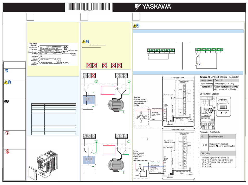
iQpump Micro control and transducer feedback signal wiring connections.
WARNING! Hazardous Voltage. Contact may cause electric shock or burn. Turn-off and lock-out system and facility power before servicing
Remove the terminal cover to gain access to the control terminals. (Step 1.)
10. SELECT START / STOP CONTROL METHOD
b1-02
NOTE: Refer to the iQpump Micro User Manual,
(Document No. TOEPYAIQPM03) to program the iQpump Micro drive
for network communication control.
11. TRANSDUCER FEEDBACK SIGNAL WIRING [REFER TO PAGE 7 OF 12 FOR 24 V POWER SUPPLY INSTALLATION]
Initialize the iQpump Micro
Set parameter A1-03 = 3330
to use 3-Wire Control
Refer to:
Quick Start Guide
TOEPYAIQPM02
The iQpump Micro is D
DEFAULT SETUP TO START/STOP FROM THE KEYPAD (digital operator). If this is the preferred start/stop method then
continue to the feedback signal connection section. Please refer to the wiring diagram below to start/stop the iQpump Micro using an external switch
or contact.
S3
S5 S6 S7 HC SC H1 RP
S2
S4
S1
Forward
Run
S3
S5 S6 S7 HC SC H1 RP
S2
S4
S1
Start
Switch
Stop
Switch
Normally
Open
Normally
Closed
Use for maintained contacts
iQpump Micro Terminals TB1-1
iQpump Micro Terminals TB1-1
3-Wire Control
2-Wire Control
Wiring Diagrams
3-Wire, 0-10V Transducer
2-Wire, 4-20mA Transducer
Set DIP switch S1 to V position
for use with 0 – 10V Transducer
See far right
NOTE: Transducer wire colors and
numbering may vary depending on
feedback device used,
consult feedback device manual.
NOTE: Transducer wire colors and
numbering may vary depending on
feedback device used,
consult feedback device manual.
Selecting Start/Stop and Speed Method
WARNING!
Read and understand
users manual before
using this equipment
.
This Quick Start
Procedure will help
you configure the
iQpump Micro (drive)
for test run operation
and basic set-up for
simplex pump
application.
Refer to the User
Manual No.
TOEPYAIQPM03,
for detailed
instructions and to
configure the drive
for each specific
installation site.
Safety Symbols in
this Document
W
WARNING!
Hazardous Voltage.
Contact may cause
electric shock or burn.
Turn-off and lock-out
system and facility
power before servicing.
WARNING!
Stay Clear- Equipment
starts automatically.
Clear all personnel
from equipment, install
shields or guards,
locate and verify
emergency SHUT-OFF
is functional. Failure to
comply may result in
serious injury to
personnel.
WARNING!
Improper Operation
Sequence. DO NOT
RUN THE MOTOR.
Failure to comply may
result in serious injury
to personnel.
WARNING!
Do not operate
equipment with covers
or guards removed.
Install or replace cover
and/or guards before
operation. Failure to
comply may result in
serious injury to
personnel.
R
R
R d
d
St
Yaskawa America, Inc., 2121 Norman Drive South, Waukegan, IL 60085, (800) YASKAWA (927-5292) Fax (847) 887-7310, [email protected], www.yaskawa.com, Document Number: TOEPYAIQPM01 11/2014 © Yaskawa America, Inc.
Page 1 of 12
iQpump Micro AC Drive
Simplex Quick Start Procedure