6 application notes, Using an output reactor, Fine tuning the carrier frequency – Yaskawa AC Drive - A1000 Option Hz High Frequency Custom User Manual
Page 14: Application notes
14
YASKAWA TM.A1000SW.056 YASKAWA AC Drive - A1000 Custom Software Supplement
6 Application Notes
6
Application Notes
Using an Output Reactor
If drive oL2 faults occur and a typical drive overload is not suspected, an output reactor or a larger drive may be required
to eliminate oL2 faults. High-speed motors typically have very low impedance, which may result in excessive peak motor
current, increased motor temperature, low speed cogging, or increased torque ripple.
It may be necessary to use an output reactor to add impedance to the system and reduce the peak ripple current and
eliminate nuisance oL2 faults. To confirm that excessive peak current caused by low motor impedance is causing the oL2
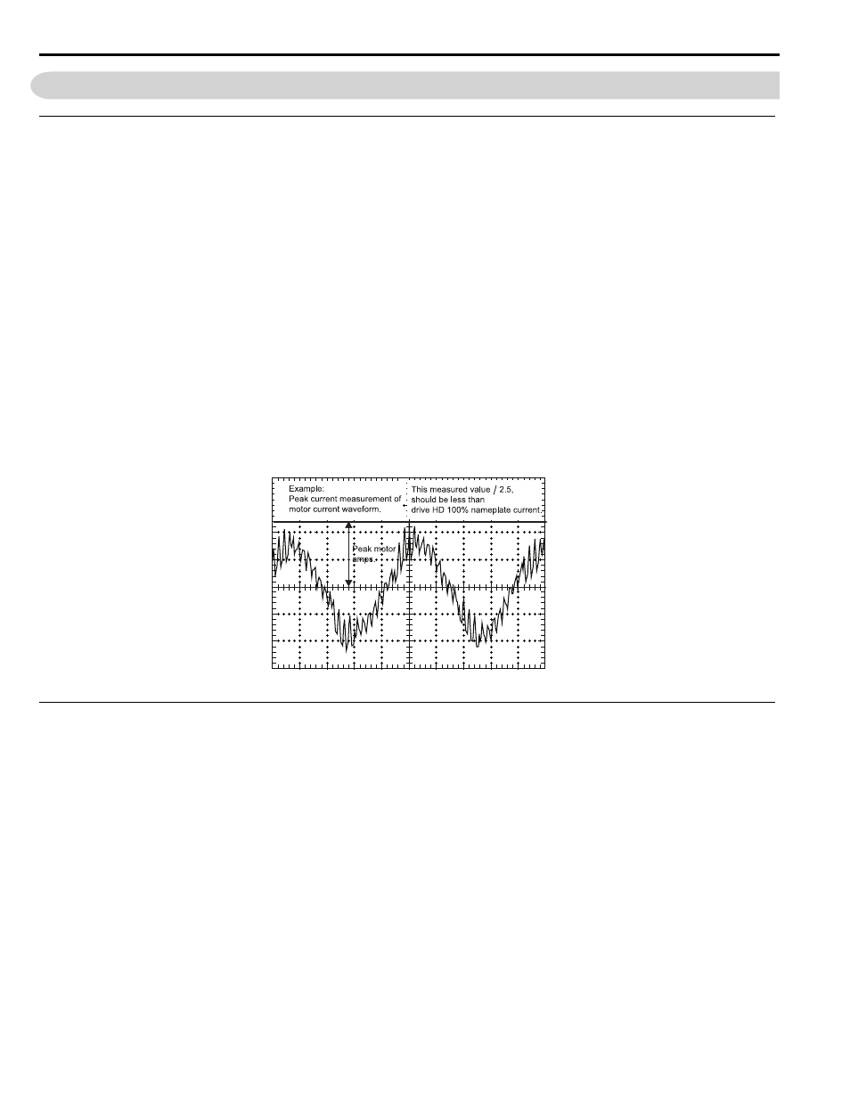
fault, measure the output current using an oscilloscope or chart recorder with a clamp-on amp meter.
Generally, the peak of the motor current waveform should not exceed 100% continuous drive HD nameplate x 2.5. This
value may vary slightly by drive model. Refer to
for an example of peak current measurement.
When using a reactor to reduce peak current, consult with the reactor manufacturer to select a reactor that will smooth out
the current waveform and also prevent a large voltage drop.
Proper reactor selection is critical in high speed applications because the reactor impedance is directly proportional to the
output frequency, which is usually given at 60 Hz. Example; a reactor operating at 600 Hz will have 10 times the
impedance and result in 10 times the voltage drop when compared to the same reactor operating at 60 Hz.
Using a larger capacity drive to allow for the additional peak current may also solve the oL2 overload trip problem. The
decision to employ an output reactor or increase drive capacity is made on a case-by-case basis.
Figure 3
Figure 3 Measuring Peak Current
Fine Tuning the Carrier Frequency
It is important to optimize the carrier frequency to improve the motor current waveform. This will improve motor speed
stability and torque performance and also limit hunting and oscillation at higher speeds.
Use one of the following setting recommendations to fine tune the carrier frequency for optimum motor performance:
1. For a flat 7.0 kHz across the speed range: Set C6-02 = “F” with C6-03 = “7.0”, C6-04 = “7.0”, and C6-05 = “0”. The
7.0 kHz across the output frequency range keeps the carrier frequency as high as possible.
2. To create a ramped carrier frequency pattern to keep the output frequency and carrier frequency at a constant
ratio:
• Set C6-02 = “F” to build a custom pattern.
• Set C6-03 = “7.0 kHz” so the motor will run at 7.0 kHz at top speed.
• Set C6-04 = “1.0 kHz” so the carrier frequency will be ramped for the greatest output frequency range.
• Solve the following formula for C6-05:
C6-05 = [7000 Hz / (2 x E1-04)]