3 application selection – Yaskawa AC Drive-A1000 User Manual
Page 10
3 Application Selection
10
YASKAWA TM.A1000SW.029 Traverse Application A1000 Custom Software Supplement
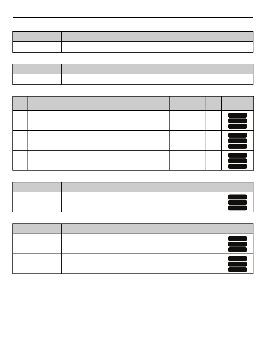
Table 5 Function Text
Table 6 Monitor Function Text
Table 7 Monitors
Table 8 Multi-function Input Settings (H1-)
Table 9 Multi-function Output Settings (H2-)
Function Group
Function Name
Digital Operator Display
P1
Disturbed Waveform Adjustment
Disturb WF Adj
Function Group
Monitor Name
Digital Operator Display
U7
Traverse Monitors
Traverse
No.
(Addr.
Hex)
Monitor Name
Digital Operator Display
Description
Analog Output
Scaling
Unit
Control Mode
Access Level
U7-02
(661h)
Absolute Slave Frequency
Slv Abs Freq
Base frequency reference summed with the
anti-phase dither.
10V: Maximum
Frequency
(E1-04)
0.01 Hz
U7-03
(662h)
Ripple Slave Frequency
Slv Ripple Freq
Anti-phase dither alone.
10V: Maximum
Frequency
(E1-04)
0.01 Hz
U7-04
(663h)
Base Slave Frequency
Slv Base Freq
Base frequency reference (before disturbed
waveform is applied).
10V: Maximum
Frequency
(E1-04)
0.01 Hz
Setting
Description
Control Mode
Access Level
80h
Disturbed WF Off
Open: Disturbed waveform enabled
Closed: Disturbed waveform disabled
Setting
Description
Control Mode
Access Level
40h
Disturb UP Sts
Open: The disturbed waveform frequency is decreasing
Closed: The disturbed waveform frequency is increasing
41h
During Disturb
Open: Disturbed waveform disabled
Closed: Disturbed waveform being generated
OLV
OLV/PM
V/f
V/f
OLV
OLV/PM
V/f
V/f
OLV
OLV/PM
V/f
V/f
OLV
OLV/PM
V/f
V/f
OLV
OLV/PM
V/f
V/f
OLV
OLV/PM
V/f
V/f