Related parameters and functions – Yaskawa AC Drive-A1000 User Manual
Page 9
3 Application Selection
YASKAWA TM.A1000SW.029 Traverse Application A1000 Custom Software Supplement
9
Related Parameters and Functions
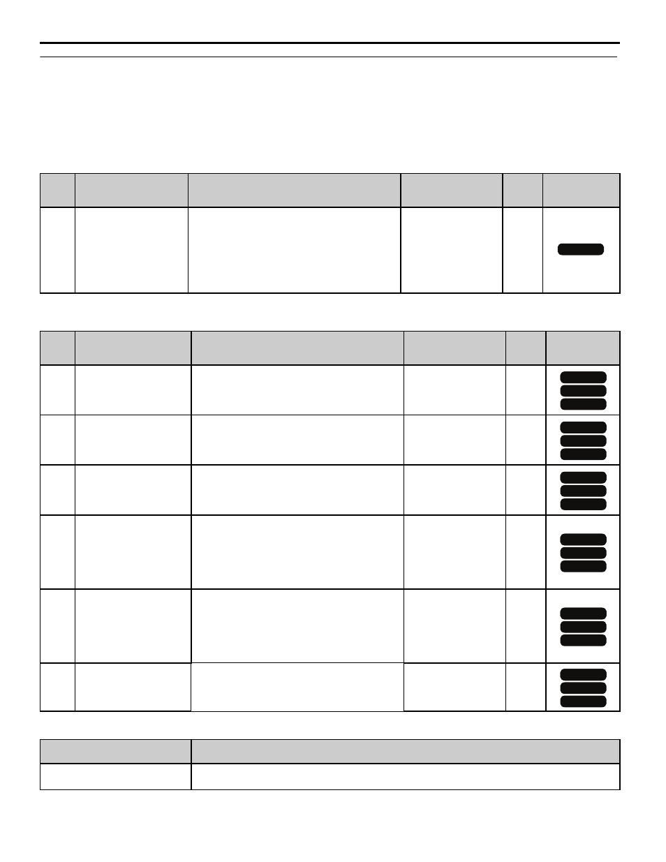
The following parameters are used to set up the drive for operation with the software. Available parameter settings are
listed based upon which drive control modes are active, as listed in the Control Mode Access Level column in the
following tables.
Confirm proper setting of the parameters beginning with
Table 2 Modified Parameters
Table 3 Additional Parameters
Table 4 Group Text
No.
(Addr.
Hex)
Parameter Name
Digital Operator
Display
Description
Values
Change
during
Run
Control Mode
Access Level
A1-00
(100h)
Language Selection
Select Language
0: English
1: Japanese
2: German
3: French
4: Italian
5: Spanish
6: Portuguese
Default: 0
Range: 0 to 6
No
No.
(Addr.
Hex)
Parameter Name
Digital Operator
Display
Description
Values
Change
during
Run
Control Mode
Access Level
P1-01
(600h)
Disturbed Waveform
Selection
Disturb WF Sel
Enables and disables the traverse disturbed
waveform function.
0: Disabled
1: Enabled
Default: 0
Range: 0 to 1
Yes
P1-02
(601h)
Disturbed Waveform
Amplitude
Disturb WF Amp
Sets the amplitude of the disturbed waveform as a
percentage of the commanded frequency reference.
Note: Setting this parameter to 0.0 disables the
Transverse function.
Default: 0.0
Range: 0.0 to 20.0 %
Yes
P1-03
(602h)
Disturbed Waveform Jump
Disturb WF Jmp
Adds a notch or jump below the peak amplitude of
the disturbed waveform when set to a non-zero
value. Set as a percentage of the Disturbed
Waveform Amplitude (P1-02).
Default: 0.0
Range: 0 to 50.0%
Yes
P1-04
(603h)
Negative Slope Time
Neg Slope Time
Sets the time for the disturbed waveform to
decelerate from the maximum value
(reference + P1 02) to the minimum value
(reference - P1-02).
Note: Setting this parameter to 0.0 seconds disables
the Transverse function.
Default: 0.0
Range: 0.0 to 120.0 s
Yes
P1-05
(604h)
Positive Slope Time
Pos Slope Time
Sets the time for the disturbed waveform to
accelerate from the minimum value
(reference - P1 02) to the maximum value
(reference + P1-02).
Note: Setting this parameter to 0.0 seconds disables
the Transverse function.
Default: 0.0
Range: 0.0 to 120.0 s
Yes
P1-06
(605h)
Slave Scan Offset
Slv Scan Offset
Monitor shift (U7-02, U7-03, and U7-04) in ms to
compensate for systematic delays.
Default: 0 ms
Range: -24 ~ 24 ms
Yes
Function Group
Group Name
Digital Operator Display
P
Traverse Group
Traverse
All Modes
OLV
OLV/PM
V/f
V/f
OLV
OLV/PM
V/f
V/f
OLV
OLV/PM
V/f
V/f
OLV
OLV/PM
V/f
V/f
OLV
OLV/PM
V/f
V/f
OLV
OLV/PM
V/f
V/f