Controller installation 4 – Irritrol KwikDial Series User Manual
Page 6
1. For safe, reliable operation, select an installation site
which can ideally provide the following conditions:
• For Indoor model controllers – Inside a garage or
other structure which will provide protection from the
weather.
• For outdoor model controllers – Protection from
irrigation spray, wind and snow. A shaded location is
recommended.
• Access to a grounded AC power source (within 4'
[1.2 m] for indoor models) which is not controlled by
a light switch or utilized by a high current load
appliance, such as a refrigerator or air conditioner.
• Access to the sprinkler control valve wiring and
optional accessory wiring.
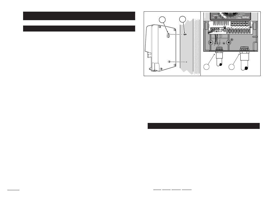
2. Drive a wood screw (provided) into the wall at eye
level (A). Leave the screw extended approximately
1
⁄
4
"
(6 mm) from the wall. See Figure 1.
Note: If installing the controller on drywall or
masonry, install screw anchors. Install the lower
screw anchor 5
1
⁄
4
" (133 mm) directly below the top
screw anchor.
3. Remove the lower cabinet access cover by squeezing
it in on the sides and pulling it directly outward from
the cabinet.
4. Hang the cabinet on the screw using the keyhole slot
on the back panel (B). Make sure the cabinet slides
down securely on the screw.
5. Install the lower mounting screw and tighten securely.
Note: Conduit and adapters are not provided. Install
conduit as required by local electrical codes.
6. Remove the power wire access cover. Remove the
conduit knockout according to the size of conduit
being used. Install
1
⁄
2
" (13 mm) conduit (C) for
power/equipment ground wires (outdoor models only)
and
3
⁄
4
" (19 mm) or 1" (26 mm) conduit (D) for valve
wires (all models).
1. Route the valve wires or wire cable from the valves,
into the controller cabinet.
Note: 18 AWG (1.0 mm
2
) multi-wire sprinkler valve
connection cable can be used. This cable is insulated
for direct burial and is color-coded to simplify
installation. It can be routed directly into the controller
through the access hole provided for valve wire
conduit (if conduit is not used).
2. Attach the white color-coded wire from the cable to
one wire from each valve solenoid. (Either solenoid
Connecting the Valves
Installing the Cabinet
Controller Installation
4
Figure 1
A
B
D
C