Irritrol KwikDial Series User Manual
Page 7
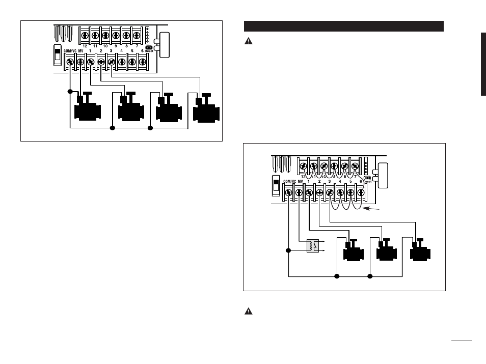
wire can be used for this connection.) This is called
the “Valve Common” wire. See Figure 2.
3. Attach a separate cable wire to the remaining wire
from each valve solenoid. Note the wire color code
used for each valve and the watering station it
controls. You will need to have this information when
connecting the valve wires to the controller.
4. Secure all wire splices using wire nut connectors. To
prevent corrosion and possible short circuits, always
use an insulated wire nut, grease cap or similar
waterproofing method.
5. At the controller end of the valve connection cable,
strip back
1
⁄
4
" (6 mm) of insulation from all cable wires
6. Secure the Valve Common wire to the terminal labeled
COM / VC. Connect the individual valve wires to the
appropriate station terminals. Connect the master valve
wire (if applicable) to the terminal labeled MV.
Note: Connecting a master valve or pump start relay
is optional and may not be required for your sprinkler
system.
CAUTION: To prevent controller damage, ensure
the pump start relay current draw does not exceed
0.4 amps. Do not connect the pump motor starter
directly to the controller.
1. Connect a wire pair to the 24 V a.c. pump start relay.
Route the wires into the controller housing with the
valve wires.
2. Connect one wire to the terminal labeled COM / VC.
Connect the remaining wire to the terminal labeled MV.
See Figure 3.
CAUTION: To prevent pump damage due to
“Dead-heading,” connect a jumper wire from any
unused station terminal to a station terminal with a
valve connected. See Figure 3.
Connecting a Pump Start Relay
5
Figure 2
Valve Common Wire
Jumper Wire
Pump Start
Relay
Figure 3
Valve Common Wire
MV
Valve 1
Valve 2
Valve 3
Valve 3
Valve 2
Valve 1