Rear panel connections – JBL Synthesis SDP-25 User Manual
Page 4
-
4
-
JBL SYNTHESIS SDP-25
Rear Panel Connections
HDMI Inputs: Connect the output of an HDMI source device to these jacks.
HDMI Outputs: Connect these jacks to the input of your video display based on the selections
made for Zone 2 Video in the Zone 2 Setup Menu (See Page 17):
• The HDMI 1 jack will always carry the selected input source and the menus when they
are in use.
• When the Zone 2 is set to the factory default of "Disable" it will carry the selected input with
no menu overlays.
• When the Zone 2 Video Setting is changed to "Enable", the HDMI 2 jack will output the
source selected for the Zone 2 system.
• When you will be using the Audio Return Channel (ARC) to feed audio from a source in the
TV or display, such as a streaming service, connect the output marked ARC on the TV to
the HDMI 1/ARC jack. Note that CEC Control must be turned On for ARC to operate (see
Page 10)
USB Audio Input: Connect this port to a USB jack on a computer, media server or other device
that will be feeding digital audio to the SDP-25. A driver may be required to play audio from your
computer via this Input. For more information please see the SDP-25 Support section of
www.jblsynthesis.com.
Serial Control Port: When using a serial control system connect this jack to the controller. We
recommend that this port only be used by installers knowledgeable in programming RS-232
control systems.
Front IR Control: When this switch is set to the default position of On (up) the Front Panel IR
Sensor will capture commands from the Remote Control. When you are using external remote
command receivers you may want to set the switch to Off (down) to avoid interference.
Coax Digital Audio Inputs: Connect the coaxial digital audio output of a source device to
these jacks.
Coax Digital Audio Outputs: Connect these jacks to the coaxial digital input of a digital audio
recorder to record a selected digital audio source.
Optical Digital Audio Outputs: Connect these jacks to the optical digital input of a digital
audio recorder to record a selected digital audio source.
Optical Digital Audio Inputs: Connect the optical digital audio output of a source device to
these jacks.
Trigger Outputs: These jacks provide a 12 volt DC signal to control the on/off status of
connected devices with external trigger control.
• Trigger Output A will send a signal whenever the SDP-25 is turned on. We recommend that
this jack be used for connection to audio power amplifiers
• Trigger Output B sends a signal to control external devices such as screens and blinds
when the Trigger B setting for any input in the Input Setup Menu is changed to On for any
input. See page 11 for more information on Trigger programming.
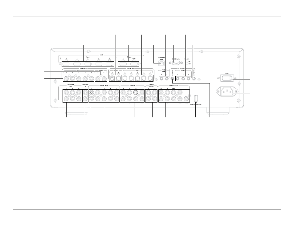
REAR PANEL CONNECTIONS
Master Power
Switch
AC Power
Cord Socket
IR
Flasher
Input
USB
Upgrade
Port
Preamp
Outputs
Analog
Audio
Outputs
7.1 Direct
Inputs
Analog
Audio
Inputs
Composite
Video
Inputs
Component
Video
Inputs
HDMI
Inputs
Optical Digital
Audio Outputs
HDMI
Outputs
USB Audio
Input
Trigger
Outputs
IR Flasher
Output
Serial
Control
Port
Front IR Control
IR Receiver Input
Optical Digital
Audio Inputs
Coax Digital
Audio Outputs
Coax Digital
Audio Inputs