Typical applications, Transferring data – Linx Technologies RXM-xxx-LR User Manual
Page 10
– –
– –
14
15
Typical Applications
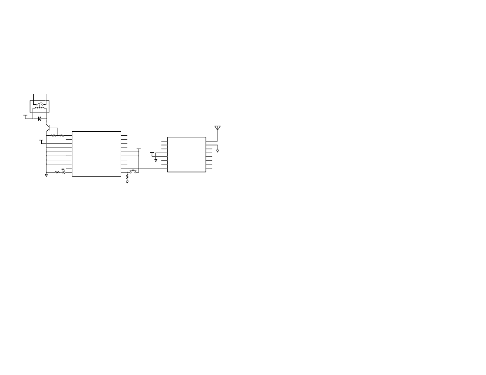
Figure 15 shows a circuit using the Linx LICAL-DEC-MS001 decoder.
This chip works with the LICAL-ENC-MS001 encoder to provide simple
remote control capabilities. The decoder detects the transmission from
the encoder, checks for errors, and if everything is correct, replicates the
encoder’s inputs on its outputs. This makes sending key presses very easy.
More information on the operation and features of the decoder can be
found in the MS Series Decoder Data Guide.
The receiver can also be connected to a GPIO of a microcontroller in
applications that use a custom protocol. No buffering is generally required
to drive a microcontroller input. Exceptions to this include systems where
the microcontroller is operating at a different voltage from the receiver. In
these cases the designer should take care to use voltage translator circuits
as appropriate.
GND
GND
VCC
NC
1
NC
2
NC
3
GND
4
VCC
5
PDN
6
RSSI
7
DATA
8
NC
9
NC
10
NC
11
NC
12
NC
13
NC
14
GND
15
ANT
16
RXM-LR
220
100k
D6
D7
SEL_BAUD0
SEL_BAUD1
GND
GND
LATCH
RX_CNTL
TX_ID
MODE_IND
D5
D4
D3
D2
VCC
VCC
D1
D0
DATA_IN
LEARN
1
2
3
4
5
6
7
8
9
10
11
12
13
14
15
16
17
18
19
20
LICAL-DEC-MS001
VCC
GND
GND
VCC
2.2k
10k
VCC
RELAY
SWITCHED OUTPUT
Figure 15: LR Series Receiver and MS Series Decoder
Transferring Data
Once a reliable RF link has been established, the challenge becomes how
to effectively transfer data across it. While a properly designed RF link
provides reliable data transfer under most conditions, there are still distinct
differences from a wired link that must be addressed. Since the LR Series
modules do not incorporate internal encoding or decoding, a user has
tremendous flexibility in how data is handled.
If the product transfers simple control or status signals such as button
presses or switch closures and it does not have a microprocessor on board
(or it is desired to avoid protocol development), consider using a remote
control encoder and decoder or a transcoder IC. These chips are available
from a wide range of manufacturers including Linx. They take care of all
encoding and decoding functions, and generally provide a number of data
pins to which switches can be directly connected. In addition, address bits
are usually provided for security and to allow the addressing of multiple
units independently. These ICs are an excellent way to bring basic remote
control / status products to market quickly and inexpensively. Additionally,
it is a simple task to interface with inexpensive microprocessors, IR, remote
control or modem ICs.
It is always important to separate the types of transmissions that are
technically possible from those that are legally allowable in the country
of intended operation. Linx Application Notes AN-00125, AN-00128
and AN-00140 should be reviewed, along with Part 15, Section 231 of
the Code of Federal Regulations for further details regarding acceptable
transmission content in the US All of these documents can be downloaded
from the Linx website at www.linxtechnologies.com.
Another area of consideration is that the data structure can affect the
output power level. The FCC allows output power in the 260 to 470MHz
band to be averaged over a 100ms time frame. Because OOK modulation
activates the carrier for a ‘1’ and deactivates the carrier for a ‘0’, a data
stream that sends more ‘0’s has a lower average output power over
100ms. This allows the instantaneous output power to be increased, thus
extending range.