Module description, Theory of operation, Data carrier – Linx Technologies RXM-xxx-LR User Manual
Page 7
– –
– –
8
9
Module Description
The LR receiver is a low-cost, high-performance synthesized AM / OOK
receiver, capable of receiving serial data at up to 10,000bps. Its exceptional
sensitivity results in outstanding range performance. The LR’s compact
surface-mount package is friendly to automated or hand production. LR
Series modules are capable of meeting the regulatory requirements of
many domestic and international applications.
The receiver's outstanding typical sensitivity of –112dBm enables system
ranges of up to 1.5 miles (2,500m) when paired with an LR Series
transmitter operating at full power and good antennas. Legal regulations
in the various countries will require the transmitter output power to be
reduced which will reduce range. Following the legal output limit for
transmitters in the United States, systems based on the LR Series can
achieve ranges of up to 3,000 feet (1,000m).
Data Slicer
LNA
VCO
PLL
XTAL
0˚
90˚
Limiter
Data Out
RSSI/Analog
∑
10.7MHz
IF Filter
Band Select
Filter
50
Ω RF IN
(Antenna)
+
-
Figure 11: LR Series Receiver Block Diagram
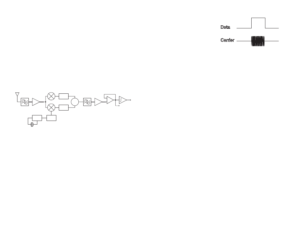
Theory of Operation
The LR Series receiver is designed
to recover data sent by an AM
or Carrier-Present Carrier-Absent
(CPCA) transmitter, also referred to
as CW or On-Off Keying (OOK). This
type of modulation represents a logic
low '0’ by the absence of a carrier
and a logic high ‘1’ by the presence
of a carrier. This modulation method affords numerous benefits. The two
most important are: 1) cost-effectiveness due to design simplicity and 2)
higher allowable output power and thus greater range in countries (such as
the U.S.) that average output power measurements over time. Please refer
to Linx Application Note AN-00130 for a further discussion of modulation
techniques.
The LR receiver utilizes an advanced single-conversion superheterodyne
architecture. Transmitted signals enter the module through a 50
Ω RF
port intended for single-ended connection to an external antenna. RF
signals entering the antenna are filtered and then amplified by an NMOS
cascode Low Noise Amplifier (LNA). The filtered, amplified signal is then
down-converted to a 10.7MHz Intermediate Frequency (IF) by mixing it
with a low-side Local Oscillator (LO). The LO frequency is generated by
a Voltage Controlled Oscillator (VCO) locked by a Phase-Locked Loop
(PLL) frequency synthesizer that utilizes a precision crystal reference. The
mixer stage incorporates a pair of double-balanced mixers and a unique
image rejection circuit. This circuit, along with the high IF frequency and
ceramic IF filters, reduces susceptibility to interference. The IF frequency is
further amplified, filtered, and demodulated to recover the baseband signal
originally transmitted. The baseband signal is squared by a data slicer and
output to the DATA pin. The architecture and quality of the components
utilized in the LR module enable it to outperform many far more expensive
receiver products.
Data
Carrier
Figure 12: CPCA (AM) Modulation