Ordering information, Absolute maximum ratings, Electrical specifications – Linx Technologies RXM-xxx-LR User Manual
Page 4
– –
– –
2
3
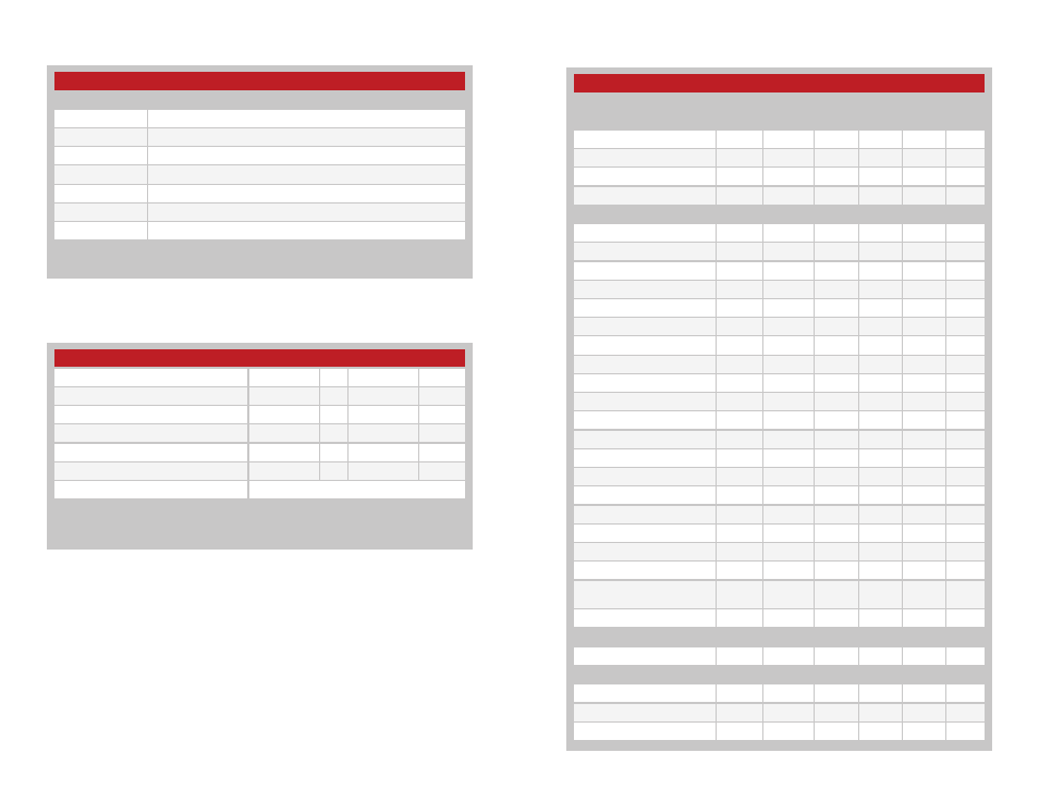
LR Series Receiver Specifications
Parameter
Symbol
Min.
Typ.
Max.
Units
Notes
Power Supply
Operating Voltage
V
CC
2.7
3.0
3.6
VDC
With Dropping Resistor
4.3
5.0
5.2
VDC
1,5
Supply Current
l
CC
4.0
5.2
7.0
mA
Power Down Current
l
PDN
20.0
28.0
35.0
µA
5
Receiver Section
Receive Frequency Range
F
C
RXM-315-LR
315
MHz
RXM-418-LR
418
MHz
RXM-433-LR
433.92
MHz
Center Frequency Accuracy
–50
+50
kHz
LO Feedthrough
–80
dBm
2,5
IF Frequency
F
IF
10.7
MHz
5
Noise Bandwidth
N
3DB
280
kHz
Data Rate
100
10,000
bps
Data Output:
Logic Low
V
OL
0.0
VDC
3
Logic High
V
OH
3.0
VDC
3
Power Down Input:
Logic Low
V
IL
0.4
VDC
Logic High
V
IH
V
CC
–0.4
VDC
Receiver Sensitivity
–106
–112
–118
dBm
4
RSSI / Analog
Dynamic Range
80
dB
5
Analog Bandwidth
50
5,000
Hz
5
Gain
16
mv /
dB
5
Voltage with No Carrier
1.5
V
5
Antenna Port
RF Input Impedance
R
IN
50
Ω
5
Timing
Receiver Turn-On Time
Via V
CC
3.0
7.0
10.0
ms
5,6
Via PDN
0.04
0.25
0.50
nS
5,6
Electrical Specifications
Ordering Information
Absolute Maximum Ratings
Ordering Information
Part Number
Description
TXM-315-LR
315MHz Transmitter
TXM-418-LR
418MHz Transmitter
TXM-433-LR
433MHz Transmitter
RXM-315-LR
315MHz Receiver
RXM-418-LR
418MHz Receiver
RXM-433-LR
433MHz Receiver
EVAL-***-LR
LR Series Basic Evaluation Kit
*** =
315, 418 (Standard), 433MHz
Receivers are supplied in tubes of 18 pcs.
Figure 2: Ordering Information
Absolute Maximum Ratings
Supply Voltage V
CC
−0.3
to
+3.6
VDC
Supply Voltage V
CC
, Using Resistor
−0.3
to
+5.2
VDC
Any Input or Output Pin
−0.3
to
V
CC
+ 0.3
VDC
RF Input
0
dBm
Operating Temperature
−40
to
+70
ºC
Storage Temperature
−40
to
+85
ºC
Soldering Temperature
+260ºC for 10 seconds
Exceeding any of the limits of this section may lead to permanent damage to the device.
Furthermore, extended operation at these maximum ratings may reduce the life of this
device.
Figure 3: Absolute Maximum Ratings