Pin assignments, Pin descriptions – Linx Technologies RXM-xxx-LR User Manual
Page 6
– –
– –
6
7
Supply Current (mA)
Supply Voltage (VDC)
5.10
5.15
5.20
5.25
5.30
5.35
5.40
2.7 2.8 2.9
3.0 3.1 3.2 3.3
3.4 3.5 3.6 3.7
3.8 3.9 4.0 4.1
4.2 4.3 4.4 4.5
4.6 4.7 4.8 4.9
5.0 5.1 5.2
With Dropping
Resistor
RFIN > –35dBm
No RFIN
Figure 7: Consumption vs. Supply
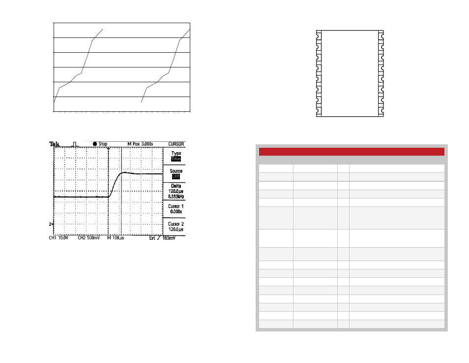
Figure 8: RSSI Response Time
Pin Assignments
NC
NC
NC
NC
NC
NC
NC
NC
NC
RSSI
GND
VCC
PDN
DATA
ANT
GND
1
2
3
4
5
6
7
8
9
10
11
12
13
14
15
16
Pin Descriptions
Figure 9: LR Series Receiver Pinout (Top View)
Figure 10: Pin Descriptions
Pin Descriptions
Pin Number
Name
I/O Description
1
NC
—
No Connection
2
NC
—
No Connection
3
NC
—
No Connection
4
GND
—
Analog Ground
5
V
CC
—
Supply Voltage
6
PDN
I
Power Down. Pulling this line low will place
the receiver into a low-current state. The
module will not be able to receive a signal in
this state.
7
RSSI
O
Received Signal Strength Indicator. This line
will supply an analog voltage that is propor-
tional to the strength of the received signal.
8
DATA
O
Digital Data Output. This line will output the
demodulated digital data.
9
NC
—
No Connection
10
NC
—
No Connection
11
NC
—
No Connection
12
NC
—
No Connection
13
NC
—
No Connection
14
NC
—
No Connection
15
GND
—
Analog Ground
16
RF IN
—
50
Ω RF Input