Using the pdn line, Power supply requirements, Esd concerns – Linx Technologies RXM-xxx-LR User Manual
Page 9
– –
– –
12
13
Power Supply Requirements
The module does not have an internal
voltage regulator, therefore it requires a
clean, well-regulated power source. While
it is preferable to power the unit from a
battery, it can also be operated from a
power supply as long as noise is less than
20mV. Power supply noise can significantly
affect the receiver sensitivity, therefore;
providing clean power to the module should
be a high priority during design.
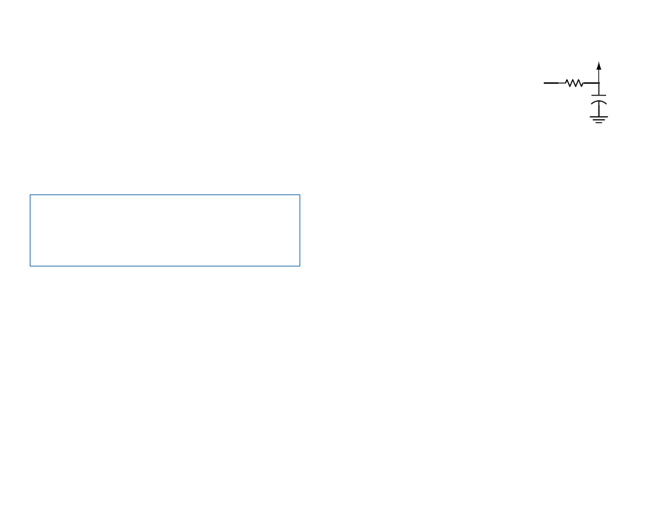
A 10
Ω resistor in series with the supply followed by a 10µF tantalum
capacitor from V
CC
to ground will help in cases where the quality of the
supply power is poor. These values may need to be adjusted depending on
the noise present on the supply line.
The module can be operated from 4.3V to 5.2V by using an external 330
Ω
series resistor to prevent V
CC
from exceeding 3.6V. This resistor can replace
the 10
Ω in the supply filter. While the receiver's current consumption is
constant and makes this possible, it is recommended to operate the
receiver from a 3.0 to 3.3V supply
ESD Concerns
The module has basic ESD protection built in, but in cases where the
antenna connection is exposed to the user it is a good idea to add
additional protection. A Transient Voltage Suppressor (TVS) diode, varistor
or similar component can be added to the antenna line. These should have
low capacitance and be designed for use on antennas. Protection on the
supply line is a good idea in designs that have a user-accessible power
port.
Figure 14: Supply Filter
+
10
Ω
10
µF
Vcc IN
Vcc TO
MODULE
Using the PDN Line
The Power Down (PDN) line can be used to power down the receiver
without the need for an external switch. This line has an internal pull-up, so
when it is held high or simply left floating, the module is active.
When the PDN line is pulled to ground, the receiver enters a low-current
(<40µA) power-down mode. During this time the receiver is off and cannot
perform any function. It may be useful to note that the startup time coming
out of power-down is slightly less than when applying V
CC
.
The PDN line allows easy control of the receiver state from external
components, like a microcontroller. By periodically activating the receiver,
checking for data, then powering down, the receiver’s average current
consumption can be greatly reduced, saving power in battery-operated
applications.
Note:
The voltage on the PDN line should not exceed V
CC
. When used
with a higher voltage source, such as a 5V microcontroller, an open
collector line should be used or a diode placed in series with the control
line (anode toward the module). Either method avoids damage to the
module by preventing 5V from being placed on the PDN line while
allowing the line to be pulled low.