Casio PX-A800BN User Manual
Page 42
E-40
Getting Ready
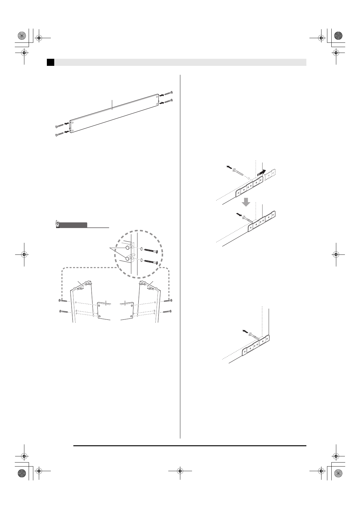
1.
Remove the four screws (two on each end)
from back board
C
.
2.
Attach side panels
A
and
B
to back board
C
. Secure side panels
A
and
B
to the back
board
C
using the screws you removed in
step 1.
•
Attach the side panels so the side of the back board C
where the joint connectors are inserted is facing
towards the back of the stand.
•
If you have trouble inserting a screw into a joint
connector screw hole, use a screwdriver to adjust the
joint connector by rotating it.
3-1.
If you plan to locate the piano and stand
where it is not against a wall, you need to
extend the anti-tip brackets at the base of
side panels
A
and
B
. Remove the two
screws (one on the outside of each side
panel) that hold the brackets, and then slide
the brackets as shown in the illustration. After
extending the anti-tip brackets, reinstall the
screws that secure them in place, but do not
tighten the screws fully at this time.
[Inside of side panels]
3-2.
If you plan to locate the piano and stand
against a wall, loosen the two screws (one on
the outside of each side panel) that secure
the brackets. You do not need to remove the
screws in this case.
•
In this case, you do not need to remove the screws.
Just loosen them.
C
C
C
A
B
IMPORTANT!
Joint connectors
• When inserting a screw into a
joint connector, keep your
finger on the joint connector
hole on the back of back board
C to make sure the joint
connector does not come out
of the hole.
PXA800_e.book 40 ページ 2013年6月18日 火曜日 午後6時18分