Kichler 16501 User Manual
Kichler Lighting
SAFETY INSTRUCTIONS
READ THIS FIRST
KEEP THESE INSTRUCTIONS
This fixture is intended for installation in accordance with the National Electric
Code (NEC) and Local code specifications. Failure to adhere to these codes
and instructions may result in serious injury and/or property damage and will
void the warranty.
WARNING – RISK OF ELECTRIC SHOCK
• Do not mount luminaire within 10 feet (3m) of a swimming pool, spa or fountain.
• This fixture is to be used only with a Kichler® low voltage lighting power unit
(transformer) rated a maximum 15 volts, 300 W per secondary (25 AMPS)
NOTE: Kit with In-Ground LED Fixture walk-over and drive-over rated for a
4500lb car or truck.
NOTE: If additional Direct Burial wire is needed, contact your local Kichler®
landscape distributor.
• 8 GA wire can be purchased in length of 250’ (76 M), 15503-BK.
• 10 GA wire can be purchased in length of 250’ (76 M), 15504-BK.
• 12 GA wire can be purchased in lengths of 100’ (30 M), 15501-BK; 250’ (76 M),
15502-BK; 500’ (152M), 15505-BK; and 1000’ (304 M), 15506-BK.
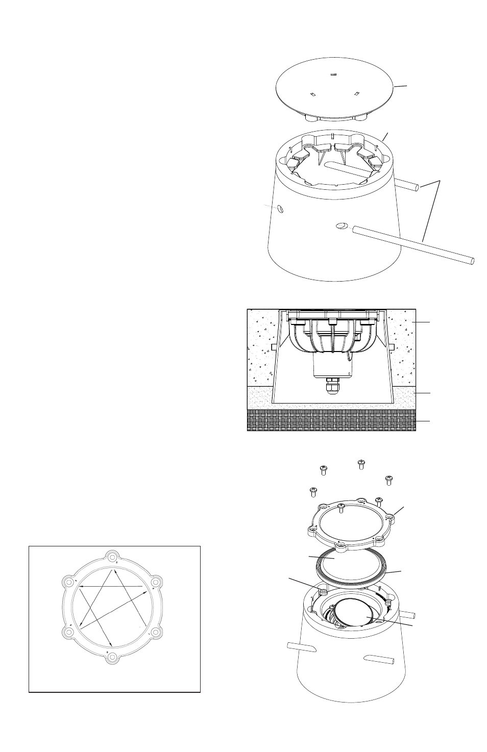
POUR KIT INSTALLATION
1. TURN OFF POWER
2. Insert the steel rods into the through holes of the housing. The rods should
protrude equally on the kit through both sides.
3. Determine desired location of kit and dig hole. Hole should be 9” (diameter)
with a depth appropriate for top of kit (including cover) to be flush with
finished grade. It is recommended that sand or pea gravel is used to set
housing and aid positioning. Leave approximately 6” of loose lead wire
from transformer inside housing.
4. Secure the cover onto the housing and pour a minimum 4” of concrete,
ensuring grade is flush with kit. Let cure. Do not remove cover until just
before installing the fixture to prevent sediment from collecting.
LUMINAIRE ASSEMBLY AND INSTALLATION
1. Remove threaded steak by removing the two (2) screws on bottom of the
fixture. Discard.
2. Using a flat-headed screw driver, remove and discard cover and wipe away
any sediment that has gathered on inner ring of the housing.
3. Before placing fixture into housing, make wire connections using supplied
Kichler
®
Pro Series Wire Connectors following the instructions included, or
using other approved wiring connection method (not supplied.) The fixture
wire is not intended for direct burial. According to the requirements of the
National Electric Code (NEC), direct burial rated wire is to be buried a
minimum of 6” [152mm] beneath the surface of the ground.
4. Install fixture, making sure fixture is completely nested in housing.
5. To aim the beam: Remove the glass sealant ring by removing the six (6)
screws on top of the fixture. Loosen the screws on the sphere retaining ring
until the sphere becomes unfixed. Aim the beam as desired. (up to 15°)
Re-tighten the screws on the sphere retaining ring until the sphere is secure
and does not rotate. Clean sealing surface, and replace glass, gasket, and
glass sealing ring. Install and torque screws to 20 ± 2 in/lbs in triangular
pattern, following the numbers screws holes 1-6.
Date Issued: 1/25/13
IS-16501-US
For warranty information please visit: http://www.landscapelighting.com/portal/warranty_page
Para informacion de la garantia por favor visite: www.landscapelighting.com/portal/warranty_page
INSTRUCTIONS FOR THE CONCRETE INSTALLATION KIT
Part No. 16501BBRP
with the In-Ground LED Fixture
Part No. 16030, 16031, 16032, 16033, 16034, 16035, 16036, 16037 and 16038
GLASS SEALING RING
ARO QUE SELLA EL VIDRIO
GLASS
VIDRIO
GASKET JOINT
JUNTA
SPHERE
CABEZAL
SPHERE RETAINING
SCREW
TORNILLO PARA FIJAR EL
CABEZAL
CONCRETE
HORMIGÓN
SAND OR
PEA GRAVEL
(RECOMMENDED)
ARENA O GRAVA
(SUGERIDA)
FOR INSTALLATION IN CONCRETE
PARA INSTALACIÓN EN HORMIGÓN
SOIL
TIERRA
COVER
TAPA
HOUSING
CAJA PARA EMPOTRAR
START
INICIO
TIGHTEN SCREWS IN TRIANGULAR PATTERN SHOWN ABOVE.
AJUSTE LOS TORNILLOS EN FORMA TRIANGULAR TAL COMO SE
MUESTRA ANTERIORMENTE.
STEEL RODS
BARRAS DE METAL