Powerfix Aluminium Insect Door Screen User Manual
Dg h i j, Kl o n m, Alu-insektenschutz-tür
PL
PL
GB
GB
GB
GB
GB
GB
Zawartość zestawu
Wskazówka: Podczas rozpakowywania należy uważać, aby przez przypadek nie
wyrzucić elementów montażowych. Bezpośrednio po rozpakowaniu należy sprawdzić, czy
zestaw jest kompletny oraz czy produkt i wszystkie elementy są w nienagannym stanie. Nie
należy montować produktu, jeżeli zestaw jest niekompletny.
4 Łączniki narożne
4 Osłony na łączniki narożne
2 Profile aluminiowe, 2040 mm
1 Profil aluminiowy, 940 mm
1 Profil poprzeczny, 940 mm
1 Aluminiowa płyta ochronna, 940 mm
1 Uszczelka szczotkowa
2 Listwy typu click, 2000 mm
4 Listwy typu click, 960 mm
3 Zawiasy, części górne
3 Zawiasy, części dolne
3 Sprężyny
2 Płyty zamykające
2 Magnesy
24 Śruby z łbem wpuszczanym
1 Uchwyt zewnętrzny
1 Uchwyt wewnętrzny
2 Listwy mocujące do płyty ochronnej
2 Łącznik poprzeczny do płyty ochronnej
1 Tkanina z włókna szklanego 1000 x 2050 mm
2 Złącza profili
2 Śruby do złączy profili
Wskazówki dotyczące bezpieczeństwa
NIEBEZPIECZEŃSTWO ODNIESIENIA
OBRAŻEŃ I UTRATY ŻYCIA PRZEZ DZIECI! Nie należy pozostawiać
dzieci z materiałem opakowaniowym i produktem bez nadzoru. Istnieje nie-
bezpieczeństwo uduszenia materiałem opakowaniowym i utraty życia wskutek zadła-
wienia. Dzieci często nie dostrzegają niebezpieczeństwa. Dzieci nie powinny mieć
dostępu do produktu. Produkt nie jest zabawką.
OSTROŻNIE! NIEBEZPIECZEŃSTWO ODNIESIENIA OBRAŻEŃ CIAŁA!
Upewnić się, czy żadna z części nie jest uszkodzona i czy wszystkie są prawidłowo
zamontowane. Nieprawidłowy montaż stwarza niebezpieczeństwo odniesienia obra-
żeń ciała. Uszkodzone części mogą wpływać na bezpieczeństwo i działanie produktu.
Montaż
Przed montażem należy upewnić się, że drzwi przystosowane są do tego produktu i nie
przekraczają maksymalnych wymiarów.
Siatka aluminiowa na drzwi przeciw owadom
Wstęp
Przed rozpoczęciem montażu należy zapoznać się z produktem. W tym celu
należy uważnie przeczytać instrukcję montażu i wskazówki dotyczące bezpie-
czeństwa. Produktu należy używać wyłącznie w sposób opisany w niniejszej
instrukcji i zgodnie z podanym w niej zakresem zastosowania. Niniejsza instrukcja powinna
być starannie przechowywana. Przekazując produkt innej osobie, należy również przeka-
zać wszystkie dokumenty.
Przeznaczenie produktu
Artykuł przeznaczony jest do użytku jako ochrona przed owadami (np. muchami) w prywat-
nych pomieszczeniach mieszkalnych. Zastosowania inne niż wyżej opisane lub dokonywanie
zmian w produkcie jest niedozwolone i może prowadzić do obrażeń ciała i / lub uszkodze-
nia produktu. Producent nie ponosi odpowiedzialności za szkody powstałe wskutek użycia
produktu w sposób niezgodny z przeznaczeniem. Produkt nie jest przeznaczony do użytku
komercyjnego.
Opis części
1
Łącznik narożny
1a
Osłona na łącznik narożny
2
Profil aluminiowy, 2040 mm
3
Profil aluminiowy, 940 mm
4
Profil poprzeczny
5
Aluminiowa płyta ochronna
6
Uszczelka szczotkowa
7a
Listwa typu click, 2000 mm
7b
Listwa typu click, 960 mm
8
Zawias, część górna
9
Zawias, część dolna
10
Sprężyna
11
Płyta zamykająca
12
Magnes
13
Śruba z łbem wpuszczanym
14
Śruba z łbem wpuszczanym
15
Śruba z łbem wpuszczanym
16
Uchwyt zewnętrzny
17
Uchwyt wewnętrzny
18
Listwa mocująca do płyty ochronnej
19
Łącznik poprzeczny do płyty ochronnej
20
Tkanina z włókna szklanego
21
Złącze profili
21a
Śruba do złącza profili
Dane techniczne
Maks. wymiary drzwi: 100 x 210 cm
Manufacturer / Service
Smartmaxx GmbH
Inselstraße 27
D-04103 Leipzig
Hotline: +49 (0) 341 99 99 43 79
E-mail: [email protected]
Information dated: 01 / 2012
Identity no.: 012012-4
the insect screen door is in contact with the door frame. In this way you utilise the optimum
closing force of the magnets
12
, (see fig. L). Now place the hinge bottom parts
9
over the
hinges
10
in the hinge top parts
8
, (fig. M). Hold the hinge bottom parts
9
to the door
frame and mark the drill holes.
Step 5
Drill the holes with a 2.5 mm drill and screw the hinge bottom parts
9
to the door frame
with two countersunk screws
13
each. Secure each of the springs
10
with a countersunk
screw
14
in the hinge bottom parts
9
, (fig. M).
Step 6
Secure each of the closure plates
11
with two countersunk screws
14
to the door frame at
the height of the magnets
12
, (see fig. N).
Assembling frame without self-closing mechanism
Follow steps 1 and 3 of the section on “Installing the frame with the self-closing mechanism”.
Step 1
Twist off the points of the hinge bottom parts
9
up to the end of the indentation (see fig. O).
Note: Do not under any circumstances twist off the complete pin. Otherwise you can no
longer use the hinge.
Step 2
Place the hinge bottom parts
9
into the hinge top parts
8
. Follow Steps 4 to 6 of the
section on “Installing the frame with the self-closing mechanism”.
Cleaning and Care
Do not under any circumstances use corrosive or abrasive cleaning agents.
Clean the fibreglass fabric and frame with a lint-free, slightly damp cloth.
Use some mild detergent if necessary.
Disposal
The packaging is made entirely of environmentally friendly materials. Dispose of
it at your local recycling centre.
Contact your local refuse disposal authority for more details of how to dispose of your
worn-out product.
Installation video
www.smartmaxx.info
Step 10
On the same aluminium profile
2
put the middle bar
4
on the middle bar connector
21
and put the aluminium profile
3
on the corner connector
1
at the top of the aluminium
profile
2
. Furnish the aluminium profile
3
with the remaining brush seal
6
and slide this
through into the corner connector
1
. Again leave ca. 3 cm protruding and cut off the brush
seal
6
, (see fig. G).
Step 11
Now finish the frame by putting the second aluminium profile
2
onto the free ends of the
aluminium profile
3
, middle bar
4
and step
5
. Use a rubber hammer if necessary for
this (see fig. G).
Step 12
Cut the long click strips
7a
into four parts, matching the top and bottom sections of the
aluminium profiles
2
. Shorten the four click strips
7b
to the measured breadth / width (B)
minus 1 cm (see fig. H).
Step 13
Lay the fibreglass fabric
20
over the frame. Start at the top left or right edge to secure the
fibreglass fabric
20
in the aluminium profile
3
with a click strip
7b
. Continue this procedure
with the click strips
7b
on the middle bar
4
and the step
5
. Proceed with the aluminium
profiles
2
and the click strips
7a
in the same way (see fig. I).
Step 14
Remove any protruding fibreglass fabric
20
with a razor blade knife (see fig. I).
Step 15
Put the caps
1a
on the corner connectors
1
, (see fig. J).
Step 16
Fasten the handle plates
16
and
17
on the middle bar
4
opposite to the later hinge side
(fig. J). For this first align just the external handle
16
vertically and centrally on the middle
bar
4
. Mark the two screw holes with a pencil on the middle bar
4
and then drill the
holes with a 3 mm drill. Place the two countersunk screws
15
through the external handle
16
into the pre-drilled holes in the profile, place the internal handle
17
on the rear side of the
frame onto the screw points and tighten this with counter-pressure by screwing in the counter-
sunk screws
15
on the middle bar
4
, (see detailed fig. J).
Assembling frame with self-closing mechanism
Step 1
Mark the position for the hinge top parts
8
. Ensure that there is a distance of at least
15 cm between the top and bottom edge of the frame and the hinge top part
8
. Drill the
holes with a 2.5 mm drill (see fig. K).
Step 2
Slide the springs
10
into the hinge top parts
8
and secure these with a countersunk screw
14
,
(see detailed picture, fig. K).
Step 3
Secure each of the hinge top parts
8
with two countersunk screws
13
on the frame
(see fig. K).
Step 4
Place the insect screen door on your door frame. Have a second person help you in this if
necessary. Align the side of the insect screen door, in which the magnets
12
are fitted (han-
dle side), with the door frame in such a way that ca. 2.5 cm of the longitudinal profile
2
of
CAUTION! RISK OF INJURY! For the assembly you require a hacksaw, a razor
blade knife and an electric drill (only for external fitting). Always refer to the operating
instructions for the required tools.
Assembling the frame
Step 1
First measure the internal measurements (H = height, B = breadth / width) of the door frame
(see fig. A).
Step 2
Deduct 2 cm from the measured height (H). Shorten the aluminium profiles
2
with the hack-
saw and a mitre block to the resulting dimension, then deburr the cut surfaces with a file
(see fig. B).
Step 3
Deduct 1 cm from the measured breadth / width (B). With the hacksaw shorten the aluminium
profile
3
, the middle bar
4
and the aluminium step
5
to the resulting dimension, then
deburr the cut surfaces with a file (see fig. B).
Step 4
For each aluminium profile
2
first slide a cross connector for step
19
and then a fastening
strip for step
18
from below into the groove provided in the aluminium profiles
2
, (see fig. C).
Step 5
For each aluminium profile
2
slide a corner connector
1
into the opening of the aluminium
profiles
2
at the bottom on the same side.
Caution: Insert the magnet
12
into the corner
connector
1
, which lies opposite to the later hinge side (see fig. D). Use a rubber hammer
if necessary to fully position the corner connectors
1
.
Step 6
Slide the brush seal
6
into the aluminium profile
2
from above all the way down in the
groove provided until it is in the corner connector
1
which has already been fitted. Leave
3 cm protruding at the top end and cut off the brush seal
6
, (see fig. D). Proceed with the
second aluminium profile
2
in the same way.
Step 7
On both aluminium profiles
2
establish the position centrally for the middle bar connectors
21
and mark these with a pencil. Drill a hole there in the inner side of each profile with a
2.5 mm drill, slide the middle bar connector
21
from above into the aluminium profile
2
and screw the connector tight with a screw
21a
through the pre-drilled hole (see fig. E).
Step 8
Insert the other two corner connectors
1
, including the protruding brush seal
6
, into the
aluminium profiles
2
at the top, ensuring that you insert the second magnet
12
into the
corner connector
1
, which is lying opposite to the later hinge side (see fig. F). Use a rubber
hammer if necessary to fully position the corner connectors
1
.
Step 9
Connect the aluminium step
5
to one aluminium profile
2
by sliding the step
5
onto the
cross connector
19
, the fastening strip
18
and the corner connector
1
. Use a rubber ham-
mer if necessary for this (see fig. G). Then slide the brush seal
6
in the groove provided in
the aluminium step through as far as the corner connector
1
and cut this off with a protru-
sion of ca. 3 cm (see detailed picture below, fig. G).
Included items
Note: When you are unpacking the components, make sure that you do not unintentionally
throw away any of the assembly materials. Check that all the items are present and that the
product and all its parts have no defects immediately after unpacking. Do not assemble the
product if any of the included items listed below are missing.
4 Corner connectors
4 Caps for corner connector
2 Aluminium profiles, 2040 mm
1 Aluminium profile, 940 mm
1 Middle bar, 940 mm
1 Aluminium step, 940 mm
1 Brush seal
2 Click strips, 2000 mm
4 Click strips, 960 mm
3 Hinge top parts
3 Hinge bottom parts
3 Springs
2 Closure plates
2 Magnets
24 Countersunk screws
1 External handle
1 Internal handle
2 Fastening strips for step
2 Cross connectors for step
1 Fibreglass fabric 1000 x 2050 mm
2 Bar connectors
2 Screws for bar connector
Safety advice
RISK OF ACCIDENT AND DANGER TO LIFE FOR
INFANTS AND CHILDREN! Never leave children unsupervised with the
packaging material or the product. The packaging material presents a suffo-
cation hazard and there is a risk of loss of life from strangulation. Children frequently
underestimate the dangers. Always keep the product out of reach of children. It is not a
toy.
CAUTION! RISK OF INJURY! Please ensure that no parts are damaged and that
all parts are correctly assembled. Incorrect assembly could lead to injury. Damaged
parts could adversely affect safety and proper function.
Assembly
Check before installation that your door is suitable for this product and does not exceed
the maximum allowable dimensions.
Aluminium Insect Door Screen
Introduction
Familiarise yourself with the product prior to assembly. Carefully read the follow-
ing assembly instructions and safety advice. Only use the product as instructed
and only for the stated areas of use. Keep these instructions in a safe place. If
passing this product on to a third party also include all the documents.
Proper use
This product is designed to provide protection against insects such as flies and is intended
for private living areas only. Any use other than that described or any modification of the
product is not permissible and may result in injury and / or damage to the product. The
manufacturer is not liable for damage caused by improper use. The product is not intended
for commercial use.
Description of Parts
1
Corner connector
1a
Cap for corner connector
2
Aluminium profile, 2040 mm
3
Aluminium profile, 940 mm
4
Middle bar
5
Aluminium step
6
Brush seal
7a
Click strip, 2000 mm
7b
Click strip, 960 mm
8
Hinge top part
9
Hinge bottom part
10
Spring
11
Closure plate
12
Magnet
13
Countersunk screw
14
Countersunk screw
15
Countersunk screw
16
External handle
17
Internal handle
18
Fastening strip for step
19
Cross connector for step
20
Fibreglass fabric
21
Bar connector
21a
Screw for bar connector
Technical data
Max. door dimensions: 100 x 210 cm
ALU-INSEKTENSCHUTZ-TüR
Montage- und Sicherheitshinweise
ALUMINIUM INSECT DOOR SCREEN
Assembly and safety advice
SIATKA ALUMINIOWA NA DRZWI
PRZECIW OWADOM
Wskazówki dotyczące montażu oraz
bezpieczeństwa
ALU SZúNYOGHáLóS AJTó
Használati- és biztonsági utasítások
ALUMINIJASTA ZAščITA PROTI
MRčESU ZA vRATA
Navodila za montažo in varnost
OCHRANA PROTI HMYZU v
HLINíKOvéM RáMU DO DvEří
Pokyny k montáži a bezpečnostní pokyny
HLINíKOvá OCHRANA PROTI HMYZU
Pokyny pre montáž a bezpečnosť
4
B
17
1 x
16
1 x
8
3 x
9
3 x
10
3 x
20
1 x
6
1 x
5
1 x
18
2 x
19
2 x
21
2 x
13
12 x
14
10 x
15
2 x
21a
2 x
11
2 x
12
2 x
1a
4 x
1
4 x
2
2 x
4
1 x
7a
2 x
7b
4 x
3
1 x
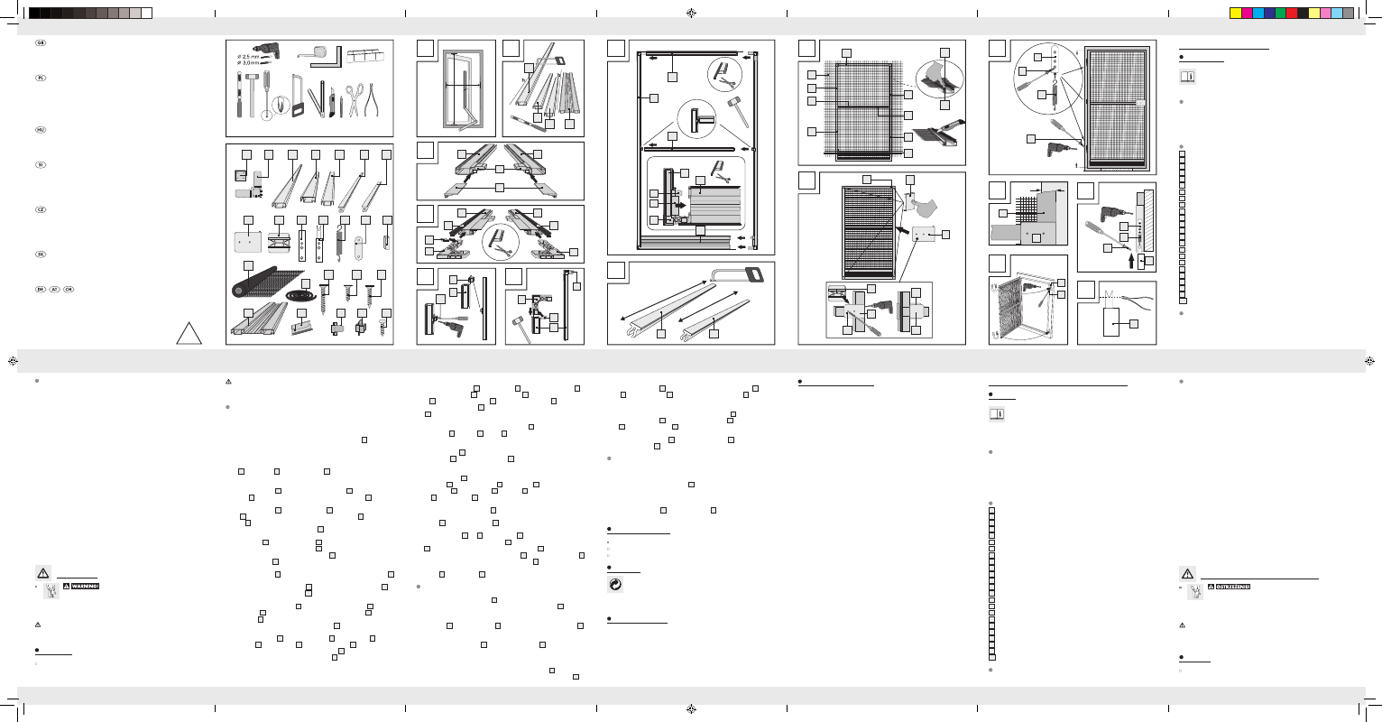
You need · Potrzebujecie · Szüksége van · Potrebujete
Potřebujete · Budete potrebovať · Sie benötigen:
A
H
B
B
2
3
4
5
D
G
H
I
J
4
5
5
7a
7b
7b
20
3
1a
15
17
16
7a
2
2
2
19
18
1
1
12
C
2
19
18
2
2
1
20
7a
7b
7a
16
16
7a
7a
7b
7b
1
17
K
L
O
N
M
11
14
2
16
11
10
14
9
9
10
13
(150 mm)
(150 mm)
E
21
2
F
12
1
2
21a
11
14
6
6
1
approx. / ca. 2,5 cm