Powerfix Aluminium Door Insect Screen User Manual
Ik j, Alu-insektenschutz-tür, Aluminium door insect screen
PL
PL
GB
GB
GB
GB
GB
GB
Q
Dane techniczne
Maks. wymiar drzwi: 100 x 210 cm
Q
Zakres dostawy
Wskazówka: Przy rozpakowywaniu produktu zwróć uwagę na to, żeby przez przeoczenie
nie wyrzucić materiału montażowego. Bezpośrednio po wypakowaniu skontroluj zakres do-
stawy pod względem kompletności oraz nienagannego stanu produktu i wszystkich części.
W żadnym wypadku nie montuj produktu, jeżeli zakres dostawy nie jest kompletny.
4 Łączniki narożne
4 Osłony na łączniki narożne
4 Profile aluminiowe A
2 Profile aluminiowe B
2 Profile poprzeczne
2 Listwy typu click 1010 mm (profil aluminiowy A)
2 Listwy typu click 910 mm (profil aluminiowy A)
4 Listwy typu click 955 mm (profil aluminiowy B)
2 Listwy zaciskowe
2 Złącza T
1 Osłona na złącze T
1 Uchwyt zewnętrzny
1 Uchwyt wewnętrzny
3 Zawiasy, części górne
3 Zawiasy, części dolne
2 Sprężyny
3 Płyty zamykające
1 Tkanina z włókna szklanego
12 Śrub z łbem wpuszczanym A
10 Śrub z łbem wpuszczanym B
3 Magnesy
1 Śruba z łbem wpuszczanym C
1 Aluminiowa płyta ochronna
2 Listwy mocujące do płyty ochronnej
2 Złącza profili
1 Uszczelka szczotkowa
1 Instrukcja montażu
Wskazówki dotyczące bezpieczeństwa
J
OstrZeżenie!
nieBeZPieCZeŃstWO UtrAtY życia i
nieBeZPieCZeŃstWO niesZCZĘŚLiWeGO WYPADKU DLA
MAŁYCH DZieCi i DZieCi! Nie pozostawiaj nigdy dzieci bez nadzoru
z materiałem opakowania i z produktem. Istnieje niebezpieczeństwo uduszenia się materia-
łem opakowania i niebezpieczeństwo utraty życia wskutek udławienia się. Dzieci często
nie doceniają niebezpieczeństw. Trzymaj stale dzieci z daleka od produktu. Produkt ten
nie jest zabawką.
siatka aluminiowa na drzwi przeciw owadom
Q
Wstęp
Przed rozpoczęciem montażu należy zapoznać się z produktem. W tym celu
należy uważnie przeczytać instrukcję montażu i wskazówki dot. bezpieczeństwa.
Produkt używać wyłącznie zgodnie z jego poniżej opisanym przeznaczeniem.
Prosimy o zachowanie instrukcji io jej dobre przechowywanie. W przypadku przekazania
produktu w ręce osoby trzeciej, prosimy o przekazanie także wszystkich należących do pro-
duktu instrukcji i innych dokumentów.
Q
Użycie zgodne z przeznaczeniem
Niniejszy artykuł jest przewidziany jako ochrona przed owadami, takimi jak na przykład
muchy w mieszkalnych pomieszczeniach prywatnych. Inne zastosowania niż opisane
uprzednio lub zmiana produktu jest niedopuszczalna i może prowadzić do obrażeń ciała
i / lub uszkodzeń produktu. Producent nie przejmuje żadnej odpowiedzialności za szkody
powstałe wskutek sprzecznego z przeznaczeniem zastosowania produktu. Produkt nie jest
przeznaczony do celów zarobkowych.
Q
Opis części
1
Łącznik narożny
1a
Osłona na łącznik narożny
2
Profil aluminiowy A
3
Profil aluminiowy B
4
Profil poprzeczny
5a
Listwa typu click 1010 mm (profil aluminiowy A
2
)
5b
Listwa typu click 910 mm (profil aluminiowy A
2
)
5c
Listwa typu click 955 mm (profil aluminiowy B
3
)
6
Listwa zaciskowa
7
Złącze T
7a
Osłona na złącze T
8
Uchwyt zewnętrzny
9
Uchwyt wewnętrzny
10
Zawias, część górna
11
Zawias, część dolna
12
Sprężyna
13
Płyta zamykająca
14
Tkanina z włókna szklanego
15
Śruba z łbem wpuszczanym A
16
Śruba z łbem wpuszczanym B
17
Magnes
18
Śruba z łbem wpuszczanym C
19
Aluminiowa płyta ochronna
20
Listwa mocująca do płyty ochronnej
21
Złącze profili
22
Uszczelka szczotkowa
Q
Cleaning and care
J
Do not under any circumstances use corrosive or abrasive cleaning agents.
j
Clean the fibreglass fabric and frame with a lint-free, slightly damp cloth.
j
Use a mild cleaning agent where necessary.
Q
installation video
For installation video visit www.feinheim.de.
Q
Disposal
The packaging is made entirely of recyclable materials, which you may dispose
of at local recycling facilities.
Contact your local refuse disposal authority for more details of how to dispose of your
worn-out product.
Q
Manufacturer / service
FeinHeim GmbH
Bischof-Otto-Str. 60
D-94486 Osterhofen
Service hotline: +49-9932-4025 897
E-mail: [email protected]
Last Information Update: 01 / 2011
Ident no.: 012011-4
step 20
Using a 2.5 mm drill bit, drill through the predrilled hole in the external handle
8
and
through the middle bar
4
(see Fig. H).
step 21
Fit the internal handle
9
to the middle bar
4
from the rear and screw the internal handle
9
and the external handle
8
together with the screw C
18
(see Fig. H).
Q
installing the frame with the self-closing mechanism
step 1
Mark the position of the hinge top part
10
. Ensure that the distance between the top and
bottom edges of the frame and hinge top part
10
is at least 15 cm. Drill the holes (see Fig. I).
step 2
Push the springs
12
into the top and bottom hinge top parts
10
and fix the spring
12
with
screw B
16
.
step 3
Fix the hinge top parts
10
to the frame with the countersunk head screw A
15
(see Fig. I).
step 4
Place the insect screen door on your door frame. If necessary, obtain the assistance of a sec-
ond person. Align the side of the insect screen door in which the magnets
17
are installed
(handle side) so that approximately 2.5 cm of the longitudinal profile is in contact with the
door frame. This ensures that you are maximising the closing force of the magnets
17
(see
Fig. J). Now fit the hinge top parts
11
over the springs
12
into the hinge top parts
11
(see
Fig. L). Hold the hinge bottom parts
10
on to the door frame and mark the positions where
the mounting holes are to be drilled.
step 5
Drill the holes and screw the hinge bottom parts
11
to the door frame with the screws A
15
.
Fix the closing springs with the screws B
16
into the hinge bottom parts
11
(see Fig. L).
step 6
Fix the closure plates
13
with the countersunk head screws B
16
to the door frame at the
same height as the magnets
17
(see Fig. M).
Q
installing the frame without the
self-closing mechanism
Follow steps 1 and 3 of the section on “Installing the frame with the self-closing mechanism”.
step 1
Clip the points of the hinge bottom parts
11
at a point no further than the end of the notch
(see Fig. K)
note: Do not clip off the complete section, otherwise you will not longer be able to use the
hinge.
step 2
Insert the hinge bottom parts
11
into the hinge top parts
10
. Follow Steps 4 to 6 of the section
on “Installing the frame with the self-closing mechanism”.
fitted later. If necessary, use a rubber hammer to tap in the corner connector
1
. Ensure that
the brush seal
22
is inserted into the corner connector
1
(see Fig. C).
step 8
Fit the middle bar
4
prepared in Step 6 and the bar connectors
21
together and then push
the middle bar
4
from above into the prepared frame by pushing the bar connectors
21
into the grooves of the aluminium profile A
2
. If necessary use a rubber hammer to tap in
the bar connectors
21
evenly (see Fig. C).
step 9
Cut the aluminium step
19
to width B less 1.2 cm using the saw. Remove any burrs from the
sawn edge using a file.
step 10
Fit the fixing strips
20
on the step
19
(see Fig. D).
step 11
Place the step
19
on the frame. If necessary, push the middle spar
4
down slightly and tap
the step
19
into the grooves provided for this purpose using a rubber hammer (see Fig. D).
Attention: Make sure you do this precisely. The step
19
is very difficult to remove again
once it has been fitted.
step 12
Insert magnets
17
into a corner connector
1
and a T-connector
7
. Ensure that the mag-
nets
17
are positioned on the opposite side to the hinges, which will be fitted later (see Fig. E).
step 13
Connect the aluminium profiles A
2
and B
3
and the remaining middle bar
4
with corner
connectors
1
and T-connectors
7
in accordance with Fig. E. Before you connect the alumin-
ium profile B
3
referred to above, push the brush seal
22
into the groove provided for this
purpose on one of the long side sides of the frame. Trim the brush using scissors, allowing it to
project 3 cm. Repeat this process on the opposite frame. Thread the brush seal
22
into the
groove of the aluminium profile B
3
. Now fit the aluminium profile B
3
.
Attention: Push
the projecting brush seals into the corner connectors when fitting the parts together.
step 14
Shorten the 2 click strips
5a
to the same length as the aluminium profiles A
2
. Shorten the
2 click strips
5b
to the length of the aluminium profiles A
2
less 10 cm (see Fig. F).
step 15
Add 1.3 cm to the lengths of the aluminium profiles B
3
and the middle bars
4
and short-
en the 4 click strips
5c
to the calculated dimensions (see Fig. F).
step 16
Place the fibreglass fabric
14
over the frame. Fix the fibreglass fabric
14
to opposite sides
with the click strips
5a
,
5b
,
5c
(see Fig. G).
note: Ensure that the fibreglass fabric
14
is adequately stretched. If necessary, repeat
Step 16.
step 17
Remove the surplus fibreglass fabric
14
using a carpet knife.
step 18
Place the caps
1a
on the corner connectors
1
and the cap
7a
on the T-connector
7
on
the same side as the hinges, which are fitted later (see Fig. H).
step 19
Fit the external handle
8
on to the remaining T-connector
7
.
1 Brush seal
1 Installation instructions
safety advice
J
WArninG!
risK OF FAtAL inJUrY AnD risK OF ACCi-
Dents FOr inFAnts AnD CHiLDren! Never leave children unattend-
ed with the packaging material or the product. There is a risk of suffocation
from the packaging materials and a risk of fatal injury by strangulation. Children often
underestimate dangers. Always keep children away from the product. The product is not
a toy.
CAUtiOn! risK OF inJUrY! Ensure that all parts are undamaged and have
been assembled appropriately. Risk of injury exists if assembled incorrectly. Damaged
parts can effect safety and function.
Q
installation
j
Check before installation that your door is suitable for this product and does not exceed
the maximum allowable dimensions.
CAUtiOn! risK OF inJUrY! Installation requires a saw, carpet knife and an
electric drill (only for external installation). Always refer to the operating instructions for
the required tools.
Q
installing the frame
step 1
First measure the internal dimensions (H = height, W = width) of the door frame (see Fig. A).
step 2
Subtract 6.5 cm from the measured height (H) and divide the value by two. Using a saw and
mitre box, shorten the aluminium profile A
2
to the calculated dimension (see Fig. B).
step 3
Subtract 1 cm from the measured width (B) and shorten the aluminium profile B
3
and one
of the middle bars
4
using a saw and mitre box to the calculated dimension (see Fig. B).
step 4
Subtract 1.2 cm from the measured width (B) and shorten the second middle bar
4
using a
saw and mitre box to the calculated dimension (see Fig. B).
step 5
Remove any burrs from the sawn surface using a file (see Fig. B).
step 6
Push a clamp strip
6
into the shorter sawn middle bar
4
and into one of the aluminium
profiles B
3
and cut off the surplus. Ensure that the angled sides of the clamp strips
6
and
aluminium profile B
3
match one another. Push a brush seal
22
into the aluminium profile B
3
as well. The seal must be 6 cm longer than the profile (see Fig. C).
step 7
Construct the bottom frame part with two aluminium profiles A
2
, the aluminium profile B
3
prepared in Step 6 and two corner connectors
1
.
Attention: Insert the magnets
17
into
the corner connector
1
. The magnets are on the opposite side to the hinges, which will be
11
Hinge bottom part
12
Spring
13
Closure plate
14
Fibreglass fabric
15
Countersunk head screw A
16
Countersunk head screw B
17
Magnet
18
Countersunk head screw C
19
Aluminium step
20
Fastening strip for step
21
Bar connector
22
Brush seal
Q
technical data
Max. door dimensions: 100 x 210 cm
Q
included in delivery
note: When opening the packaging, please make sure not to accidentally throw away
assembly materials. Please check immediately on unpacking that the delivery is complete
and that the product and all parts are in perfect condition. Do not under any circumstances
assemble the product if the delivery is incomplete.
4 Corner connectors
4 Caps for corner connector
4 Aluminium profiles A
2 Aluminium profiles B
2 Middle bars
2 Click strips 1010 mm (aluminium profile A)
2 Click strips 910 mm (aluminium profile A)
4 Click strips 955 mm (aluminium profile B)
2 Clamp strips
2 T-connectors
1 Cap for T-connector
1 External handle
1 Internal handle
3 Hinge top parts
3 Hinge bottom parts
2 Springs
3 Closure plates
1 Fibreglass fabric
12 Countersunk head screws A
10 Countersunk head screws B
3 Magnets
1 Countersunk head screw C
1 Aluminium step
2 Fastening strips for step
2 Bar connectors
Aluminium Door insect screen
Q
introduction
Please familiarise yourself with the product prior to assembly. Carefully read the
following assembly instructions and safety tips. Only use the unit as described and
for the specified applications. Store these instructions in a safe place. If passing
this product on to a third party also include all documents.
Q
intended Use
This article is designed to provide protection against insects such as flies and is intended for
indoor use only. Any use other than previously mentioned or any product modification is pro-
hibited and can lead to injuries and / or product damage. The manufacturer is not liable for
any damages caused by any use other than for the intended purpose. The product is not
intended for commercial use.
Q
Description of parts and features
1
Corner connector
1a
Cap for corner connector
2
Aluminium profile A
3
Aluminium profile B
4
Middle bar
5a
Click strip 1010 mm (aluminium profile A
2
)
5b
Click strip 910 mm (aluminium profile A
2
)
5c
Click strip 955 mm (aluminium profile B
3
)
6
Clamp strip
7
T-connector
7a
Cap for T-connector
8
External handle
9
Internal handle
10
Hinge top part
ALU-inseKtensCHUtZ-tür
Montage- und Sicherheitshinweise
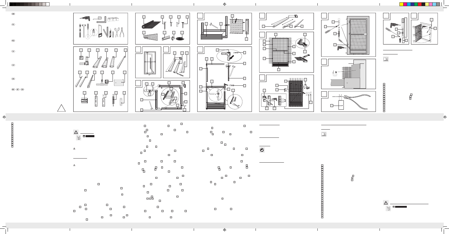
You need · Potrzebujecie · Szüksége van · Potrebujete · Potřebujete
Budete potrebovať · Sie benötigen:
ALUMiniUM DOOr inseCt sCreen
Assembly and safety advice
siAtKA ALUMiniOWA nA DrZWi
PrZeCiW OWADOM
Wskazówki dotyczące montażu oraz
bezpieczeństwa
ALU sZúnYOGHáLós AJtó
Használati- és biztonsági utasítások
ALUMiniJAstA ZAščitA PrOti
MrčesU ZA vrAtA
Navodila za montažo in varnost
OCHrAnA PrOti HMYZU v HLiníKO-
véM ráMU DO Dveří
Pokyny k montáži a bezpečnostní pokyny
HLiníKOvá OCHrAnA PrOti HMYZU
Pokyny pre montáž a bezpečnosť
4
M
L
10
15
11
16
12
13
ø 2,5 mm
B
A
1a
4 x
5c
4 x
5b
2 x
6
2 x
9
1 x
10
3 x
11
3 x
12
2 x
13
3 x
7
2 x
7a
1 x
8
1 x
1
4 x
2
4 x
4
2 x
5a
2 x
3
2 x
14
1 x
19
1 x
20
2 x
21
2 x
22
1 x
16
10 x
17
3 x
18
1 x
15
12 x
H
B
B
2
4
3
C
D
F
G
H
E
2
4
4
3
3
6
17
21
21
2
22
2
1
22
4
19
5c
14
20
5c
9
1a
18
8
8
5a
19
1
2
7
22
7
17
2
17
5a
14
5a
5c
5b
7a
7
5b
5c
5a
5b
5c
1
1
3
4
22
+ approx./
ca. 3,0 cm
1
I
K
J
10
16
11
12
15
(150 mm)
(150 mm)
approx./ca. 2,5 cm
61062_Alu-Insektenschutztür_Content_LB4.indd 1
03.02.11 09:19