Powerfix ALUMINIUM INSECT SCREEN BLIND User Manual
Dg h e f, Ab c, Kl m
PL
GB
GB
GB
GB
GB
GB
roleta aluminiowa chroniąca przed owadami
Q
Wstęp
Przed rozpoczęciem montażu należy zapoznać się z produktem. W tym celu
należy uważnie przeczytać instrukcję montażu i wskazówki dot. bezpieczeństwa.
Produkt używać wyłącznie zgodnie z jego poniżej opisanym przeznaczeniem.
Prosimy o zachowanie instrukcji io jej dobre przechowywanie. W przypadku przekazania
produktu w ręce osoby trzeciej, prosimy o przekazanie także wszystkich należących do pro-
duktu instrukcji i innych dokumentów.
Q
Użycie zgodne z przeznaczeniem
Niniejszy artykuł jest przewidziany jako ochrona przed owadami, takimi jak na przykład
muchy w mieszkalnych pomieszczeniach prywatnych. Inne zastosowania niż opisane
uprzednio lub zmiana produktu jest niedopuszczalna i może prowadzić do obrażeń ciała
i / lub uszkodzeń produktu. Producent nie przejmuje żadnej odpowiedzialności za szkody
powstałe wskutek sprzecznego z przeznaczeniem zastosowania produktu. Produkt nie jest
przeznaczony do celów zarobkowych.
Q
Opis części
1
Kaseta na roletę
1a
Pokrywa obudowy, kaseta na roletę (strona nacięta)
1b
Adapter (zainstalowany na pokrywie obudowy)
1c
Śruba do pokrywy obudowy
1d
Listwa uchwytu
1e
Tkanina z włókna szklanego
2
Prowadnica
3
Listwa blokująca
4
Sznurek do pociągania
5
Oprawa uchwytu
6
Zasuwa
7
Hak zamykający
8
Uszczelka szczotkowa, listwa uchwytu
9
Zaślepka, listwa uchwytu
10
Sprężyna naciskowa
11
Bolec zaciskowy
12
Końcówka, kaseta na roletę
12 a
Osłona śruby do końcówki
13
Śruba zaciskowa do kasety na roletę oraz prowadnicę
13 a
Nakrętka do śruby zaciskowej
14
Element wewnętrzny stopki zaciskowej
14 a
Osłona śruby elementu wewnętrznego stopki zaciskowej
15
Stopka zaciskowa
16
Korba
17
Śruby (montaż alternatywny)
18
Kołki (montaż alternatywny)
Q
Manufacturer / service
FeinHeim GmbH
Bischof-Otto-Str. 60
D-94486 Osterhofen
Service hotline: +49-9932-4025 897
E-mail: [email protected]
Last Information Update: 02 / 2011
Ident no.: 022011-4
j
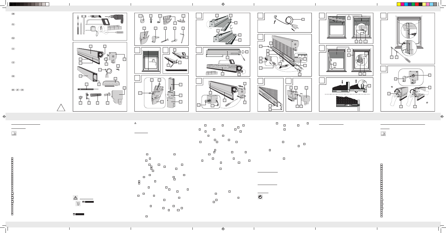
Release the locking thread
20
through a half-turn anticlockwise using the crank
16
.
attention: Do not let go of the crank
16
. The locking thread
20
can be seen to move
out. Now turn the crank 5 turns in the same direction. After successfully tensioning the
spring, you must turn the locking thread
20
carefully through a half-turn clockwise to
lock it again.
attention: Do not use too much force when relocking.
note: You can add 7 turns anticlockwise to the preset 23 turns to bring the retractor
spring to its maximum tension (30 turns) (see Fig. O).
detensioning the retractor spring if it has too much tension:
j
To do this, release the locking thread
20
again through a half-turn anticlockwise using
the crank.
attention: Do not let go of the crank. Draw the locking thread
20
approx.
2 cm outwards using the crank and then grip the locking thread
20
between your
thumb and index fi nger.
attention: Do not, under any circumstances, let go of the
locking thread
20
, otherwise the retractor spring will become completely detensioned.
j
Now turn the crank the desired number of turns clockwise to reduce the tension in the
retractor spring. From the factory preset tension, you can turn the crank a maximum
number of 7 turns clockwise to detension the spring. After successfully reducing the tension,
you must now move the locking thread
20
carefully into the roller blind cassette and
then lock it by turning it through a half-turn anticlockwise (see Fig. O).
attention: Do
not use too much force when relocking.
note: If the locking thread slips out of your fi n-
gers, then you must retension the retractor spring as described in the section “Tensioning
the retractor spring”.
Q
Cleaning and care
J
Do not under any circumstances use corrosive or abrasive cleaning agents.
j
Clean the fi breglass fabric and frame with a lint-free, slightly damp cloth.
j
Use a mild cleaning agent where necessary.
Q
installation video
For installation video visit www.feinheim.de.
Q
disposal
The packaging is made entirely of recyclable materials, which you may dispose
of at local recycling facilities.
Contact your local refuse disposal authority for more details of how to dispose of your
worn-out product.
step 8
Slide the cord
4
fi rst and then the handles
5
along with the sliding stop bars
6
(from
both ends) into the slot provided for that purpose in the handle profi le
1d
. Shorten the brush
seal
8
of the handle profi le
1d
by a total of 5 cm. Push the clips
7
on both ends of the
handle profi le
1d
into the same slot as the one in which the brush seal sits
8
(see Fig. H).
step 9
Place the end caps
9
on the handle profi le
1d
(see Fig. I).
step 10
Insert the compression springs
10
and the friction pins
11
into the recess of the cassette end
cover
1a
and place the end caps
12
on to the roller blind cassette
1
(see Fig. J).
note: Call in a second person capable of helping you with the next few steps in the instal-
lation of the insect screen window roller blind into the window reveal.
step 11
Clamp the roller blind cassette
1
into the window reveal and fi x the cassette in place by
tightening the clamping bolts
13
on the roller blind cassette
1
using the Allen key
19
. Then
put on the end caps
12 a
(see Fig. K).
step 12
Thread the guide channels
2
top into the roller blind cassette
1
and clamp the guide
channels
2
in the window reveal. Fix the channels in place by tightening the clamping bolts
13
to the clamping ends using the Allen key
19
. Then put on the end caps
14 a
(see Fig. L).
Q
stopping, opening and closing the blind
If the blind is pulled down fully, the clips
7
engage. To release the blind, press it downwards
and outwards (towards the window). The clips release and the blind can be opened, see
Fig. M (I).
Sliding the handles towards the sides of the blind (with reference to the blind in the installed
position) fi xes the blind in position. Sliding the handles inwards from the sides of the blind
again releases the blind. The blind can be stopped at any intermediate height, see Fig. M (II).
Q
alternative installation (screwed)
You can also screw the window roller blind into the window reveal (see Fig. N).
j
To do this, follow Steps 1 to 11. Then measure approx. 12 cm in from the top and bottom
and mark the hole positions on the guide channels
2
.
j
Remove the guide channels
2
again and drill the holes in them using a 4 mm drill bit.
j
Mark the positions of the holes on the window reveal and drill the holes with a ø 6 mm
masonry drill bit. Clean out the drilled holes and insert the dowels
18
.
j
Then put the guide channels
2
back into the reveal as shown in Fig. K and fasten them
in place with the screws
17
.
setting the retractor spring:
note: Read through this step carefully and refer closely to Fig. O.
tensioning the retractor spring:
The insect screen window roller blind is set in the factory with 23 crank rotations. If you fi nd
this setting is too low, you can increase the tension of the retractor spring. To do this, proceed
as follows:
CaUtiOn! risk OF injUrY! Ensure that all parts are undamaged and have
been assembled appropriately. Risk of injury exists if assembled incorrectly. Damaged
parts can eff ect safety and function.
Q
installation
j
Check before installation that your window reveal is suitable for this product and does
not exceed the maximum allowable dimensions. The depth of the reveal must not be less
than 6.5 cm. If necessary, have a second person help you with the installation.
step 1
Measure the height (H) and width (B) of your window reveal (see Fig. A).
attention: Take into account any diff erences in length between the left and right window
reveal.
step 2
Align the stop strips
3
, which are inserted into the guide channels
2
, on the later sawn end
fl ush with the profi le edge. Subtract 6.5 cm from the measured height H and transfer this value
on to the guide channels
2
. Cut the channels to length using a hacksaw.
attention: Ensure
that the stop strips
3
do not become displaced (see Fig. B).
step 3
Insert the clamping bolt
13
and the nut
13 a
into the clamping end internal part
14
. Put the
clamping end internal part
14
and clamping end
15
together. Ensure that the lug on the
clamping end internal part
14
slides into the slot in the clamping end
15
. Then push the two
parts on to the guide channel
2
(see Fig. C).
step 4
Pull the fi breglass fabric
1e
slightly out and wrap it around the roller blind cassette
1
, so
that the fabric
1e
cannot move back into the roller blind cassette
1
. If necessary, obtain
the assistance of a second person. Now pull off the handle profi le
1d
from the fi bre glass
fabric
1e
. Turn the handle profi le
1d
through 180° and slide it back on to the fi breglass
fabric
1e
(see Fig. D).
step 5
Take off the end cover
1a
of the roller blind cassette
1
from the cut end (identifi ed with
self-adhesive measurement label). Bring the handle profi le
1d
and the roller blind cassette
1
together as shown in Fig. E.
attention: Ensure that the handle profi le
1d
and the roller
blind cassette
1
are fl ush with one another on the cut end. Now cut the roller blind cas-
sette
1
and the handle profi le
1d
to the length B -1.5 cm (see Fig. E). Then remove any
burrs from the sawn edges using a fi le.
attention: The roller blind cassette
1
has a retractor
spring, which means that the roller blind cassette
1
can be sawn no shorter than 70 cm in
length.
step 6
Fix the cassette end cover
1a
back on to the roller blind cassette
1
(see Fig. F). Ensure that
the tab of the locator on the cassette end cover
1a
and the tab on the adapter
1b
engage
in the slot of the blind fabric roll. Insert the clamping bolt
13
and the nut
13 a
into both the
cassette end covers (see Fig. F).
step 7
Assemble the cord
4
as shown in Fig. G.
Q
technical data
Max. dimensions of the window reveal: 130 x 160 cm (W x H)
Q
included in delivery
note: When opening the packaging, please make sure not to accidentally throw away
assembly materials. Please check immediately on unpacking that the delivery is complete
and that the product and all parts are in perfect condition. Do not under any circumstances
assemble the product if the delivery is incomplete.
1 Roller blind cassette with handle profi le and brush seal
1 Cassette end cover (cut end)
2 Screws for cassette end cover
1 Fibreglass fabric
2 Guide channels
2 Stop strips
1 Cord
2 Handles
2 Sliding stop bars
2 Clips
2 Handle profi le end caps
2 Compression springs
2 Friction pins
2 Cassette end caps
2 Bolt covers for end cap
4 Clamping bolts for roller blind cassette and guide channel
4 Nuts for clamping bolt
2 Clamping end internal parts
2 Bolt covers for clamping end internal parts
2 Clamping ends
1 Crank
4 Screws (alternative installation)
4 Dowels (alternative installation)
1 Allen key
1 Installation instructions
safety advice
J
WarninG!
risk OF Fatal injUrY and risk OF aCCi-
dents FOr inFants and CHildren! Never leave children unattend-
ed with the packaging material or the product. There is a risk of suff ocation
from the packaging materials and a risk of fatal injury by strangulation. Children often
underestimate dangers. Always keep children away from the product. The product is not
a toy.
WarninG!
risk OF lOss OF liFe! Do not lean too far out of the window when
you are installing, removing or cleaning the product.
aluminium insect screen blind
Q
introduction
Please familiarise yourself with the product prior to assembly. Carefully read the
following assembly instructions and safety tips. Only use the unit as described and
for the specifi ed applications. Store these instructions in a safe place. If passing
this product on to a third party also include all documents.
Q
intended Use
This article is designed to provide protection against insects such as fl ies and is intended for
indoor use only. Any use other than previously mentioned or any product modifi cation is pro-
hibited and can lead to injuries and / or product damage. The manufacturer is not liable for
any damages caused by any use other than for the intended purpose. The product is not
intended for commercial use.
Q
description of parts and features
1
Roller blind cassette
1a
Cassette end cover (cut end)
1b
Adapter (placed on cassette end cover)
1c
Screw for cassette end cover
1d
Handle profi le
1e
Fibreglass fabric
2
Guide channel
3
Stop strip
4
Cord
5
Handle
6
Sliding stop bar
7
Clip
8
Brush seal handle profi le
9
Handle profi le end cap
10
Compression spring
11
Friction pin
12
Cassette end cap
12 a
Bolt cover for end cap
13
Clamping bolt for roller blind cassette and guide channel
13 a
Nut for clamping bolt
14
Clamping end internal part
14 a
Bolt cover for clamping end internal part
15
Clamping end
16
Crank
17
Screws (alternative installation)
18
Dowel (alternative installation)
19
Allen key
20
Locking thread (installed in cassette end cover (see Fig. O))
alU-insektensCHUtz-
FensterrOllO
Montage- und Sicherheitshinweise
alUMiniUM inseCt sCreen blind
Assembly and safety advice
rOleta alUMiniOWa CHrOniĄCa
Przed OWadaMi
Wskazówki dotyczące montażu oraz bezpieczeństwa
alU szÚnYOGHÁlÓs ablakredŐnY
Használati- és biztonsági utasítások
alUMinijasti Okenski rOlO za
zaščitO Pred MrčesOM
Navodila za montažo in varnost
OCHrannÁ rOleta PrOti HMYzU
V HlinÍkOVÉM rÁMU
Pokyny k montáži a bezpečnostní pokyny
HlinÍkOVÁ, PrOtiHMYzOVÁ
OkennÁ rOleta
Pokyny pre montáž a bezpečnosť
4
You need · Potrzebujecie · Szüksége van · Potrebujete · Potřebujete
Budete potrebovať · Sie benötigen:
3 m
1
1 x
1c
2 x
5
2 x
12
2 x
6
2 x
7
2 x
10
2 x
11
2 x
9
2 x
1b
1 x
3
1 x
1 e
1 x
8
1 x
2
2 x
4
1 x
1a
1 x
1d
1 x
D
G
H
E
F
12 a
2 x
4 x
13 a
2 x
4 x
13
2 x
15
1 x
16
4 x
17
4 x
18
1 x
19
2 x
14
14 a
3 m
A
B
C
2
3
1d
1e
8
7
4
8
7
1d
1d
1a
1d
3
14
15
13
9
1d
15
13 a
13
2
2
1
1
1 e
1
1d
1d
4
7
6
5
5
1
1c
10
12
1
1a
11
1
1a
14
H
H - 6,5 cm
180°
B
min. 70 cm
B - 1,5 cm
13 a
I
J
ø 4 mm
ø 6 mm
K
L
M
12 a
19
13
1
1
14 a
19
13
(I)
(II)
2
2
7
-
+
N
O
18
17
ca. 12 cm
ca. 12 cm
max. 7
max. 7
16
20
20
16
16
20
61065_Insektenschutz-Fensterrollo_Content_LB4.indd 1
25.02.11 15:01