Multi-Contact MA213 User Manual
Page 6
Advanced Contact Technology
6 / 16
www.multi-contact.com
4
5
6
7
8
9
10
11
Montaje de los soportes de
los contactos
Assembly of the contact
carrier
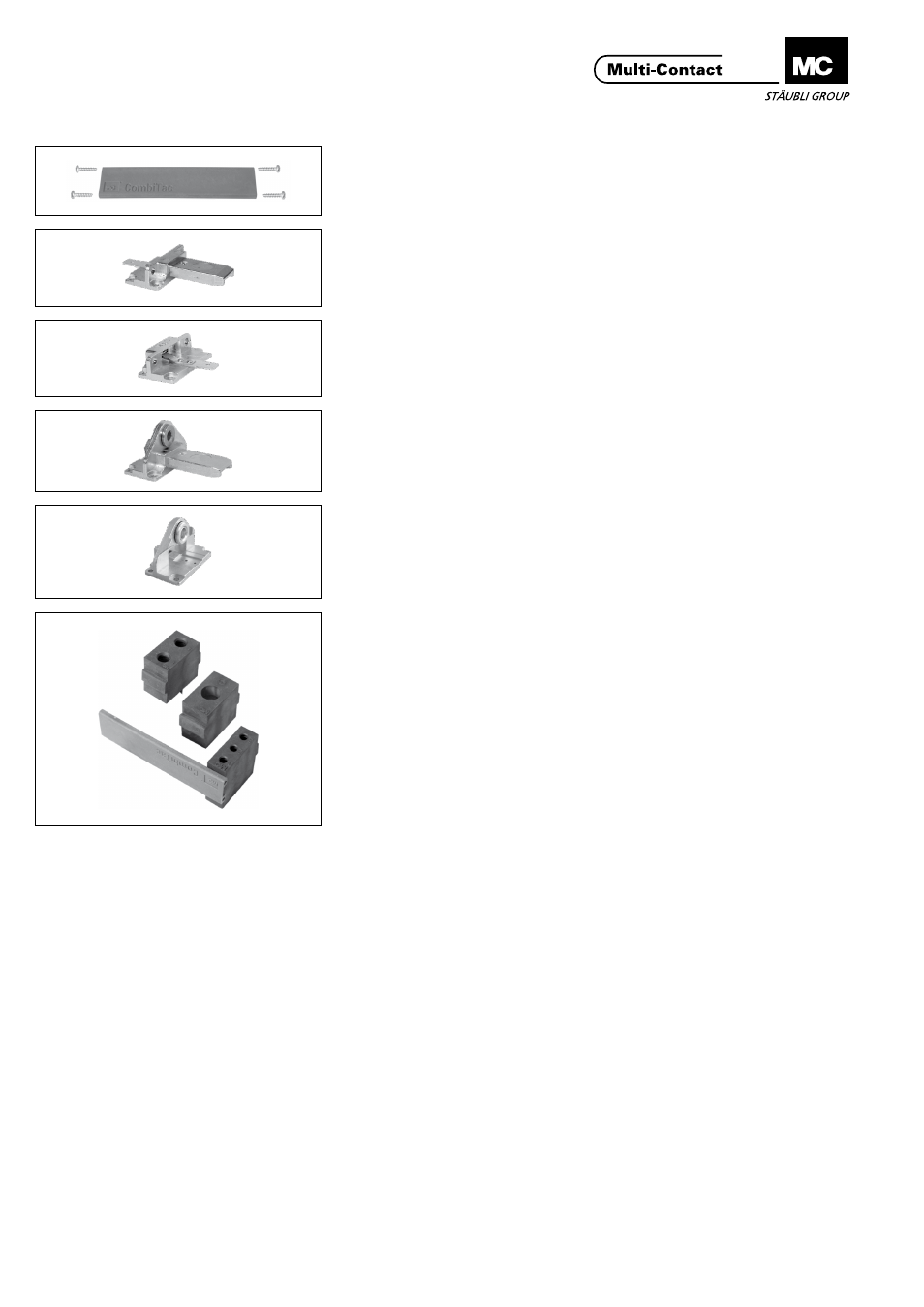
Partes individuales:
Individual parts
(ill. 4)
Carril de soporte e viti con testa a
croce
(ill. 4)
Supporting rail with cross recessed
screws
(ill. 5)
Terminación para caja DIN macho
(ill. 5)
End piece for DIN housings, pins
(ill. 6)
Termincación para caja DIN hembra
(ill. 6)
End piece for DIN housings, sockets
(ill. 7)
Terminación para Rack macho
(ill. 7)
End piece for panel mounting, pins
(ill. 8)
Terminación para Rack hembra
(ill. 8)
End piece for panel mounting, sockets
(ill. 9)
Colocar los soportes de los contactos
en el orden deseado sobre el carril
soporte� El logo MC de la tapa lateral
orientado hacia arriba�
(ill. 9)
Clamp on all the contact carriers in
the desired sequence on a support-
ing rail�
The MC logo must be upside
down on the plug side of the rails�
(ill. 10)
Colocar el segundo carril soporte�
(ill. 10)
Clamp on the second rail
(ill. 11)
Fijar ambas terminaciones para las
cajas macho mediante 8 tornillos� Par
de apriete 0,5Nm�
(ill. 11)
Attach both end pieces for pin carriers
with 8 cross recessed screws�
Tightening torque 0,5Nm�