Serial communications connections – Precision Digital PD8-765 User Manual
Page 21
PD8 Series Explosion-Proof Instrument Supplemental Manual
21
Serial Communications Connections
ProtEX-MAX instruments with integrated P
RO
V
U
and Trident X2 functionality have a 5
position terminal block for connecting RS-485 serial devices. See Model Number
Descriptions on page 4 for details on ProtEX-MAX integrated instruments.
Vigilante II integrated models do not have serial communications.
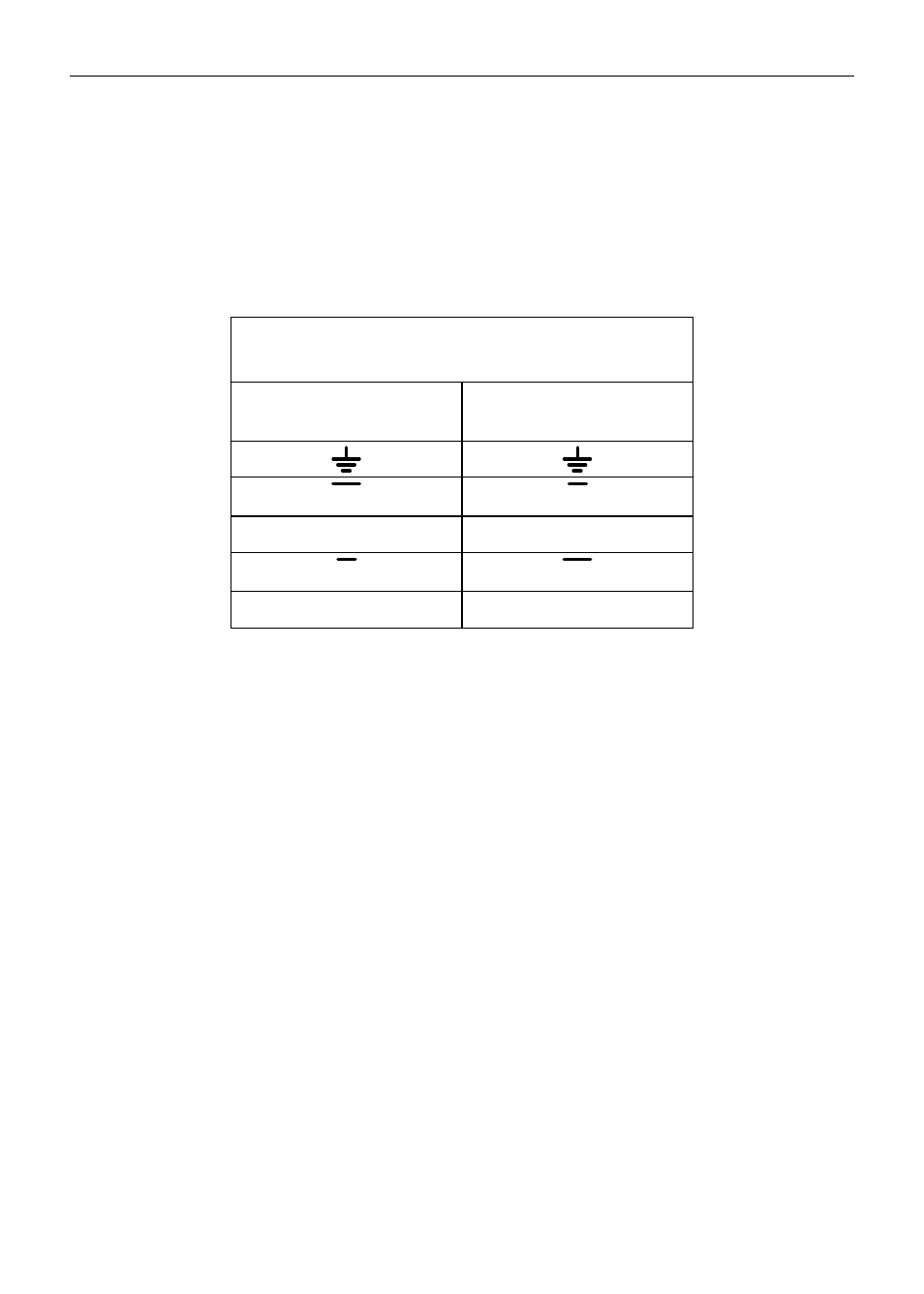
Figure 7 details the wiring connections from the ProtEX-MAX to an RS-485 serial
converter (such as the PDA7485 or PDA8485) for a four-wire network.
ProtEX-MAX to RS-485
Serial Converter Connections
RS-485 Serial
Converter
ProtEX-MAX RS-485
Connections
DO
DI
DO
DI
DI
DO
DI
DO
Figure 7: ProtEX-MAX Connections to a Serial Converter
(P
RO
V
U
& Trident X2 Integrated Instruments Only)
Baud rates are adjustable and handled by the P
RO
V
U
or Trident X2 (see the included
manuals for more details on programming the serial communications settings).
The ProtEX-MAX has three diagnostic LEDs: a Power (P) LED to show when the
module is powered properly, a Transmit Data (TX) LED to show when the module is
being transmitted to by the PC side, and a Receive Data (RX) LED to show when the
module is sending data to a receiving device.
The following diagrams detail how to connect the RS-485 serial communications from
the ProtEX-MAX to a RS-485/RS-232 serial converter (PDA7485) in four wire and
two wire configurations.