Rose Electronics UltraMatrix AV VGA 8 User Manual
Page 12
8
UltraMatrix AV Installation and Operations Manual
1. Select 2 for the “Router Count”.
2. The “Advanced Configuration” check box is used for configuring more than 1 UltraMatrix AV unit.
Leave this check box blank for configuring multiple units using “Y” video, audio, and serial cables.
3. Select AV-16x16 for “Router Type 00”.
4. Select AV-16x16 for “Router Type 01”
5. A/V Split check box is not available
6. Select the “Com Port” to connect the serial communication cable to.
7. The “Router Timeout” field set how many seconds the program will wait for the UltraMatrix AV unit to respond
to commands. Example: 2.5 will wait 2 and 1/2 seconds. If 0 is entered, the unit will not wait for a response and
any errors that occur will not display.
8. The “Comm Type” field set to “Type A”
9. When all fields are set to the correct values, click on the “OK” tab. The matrix OSD will display as
shown in Figure 6
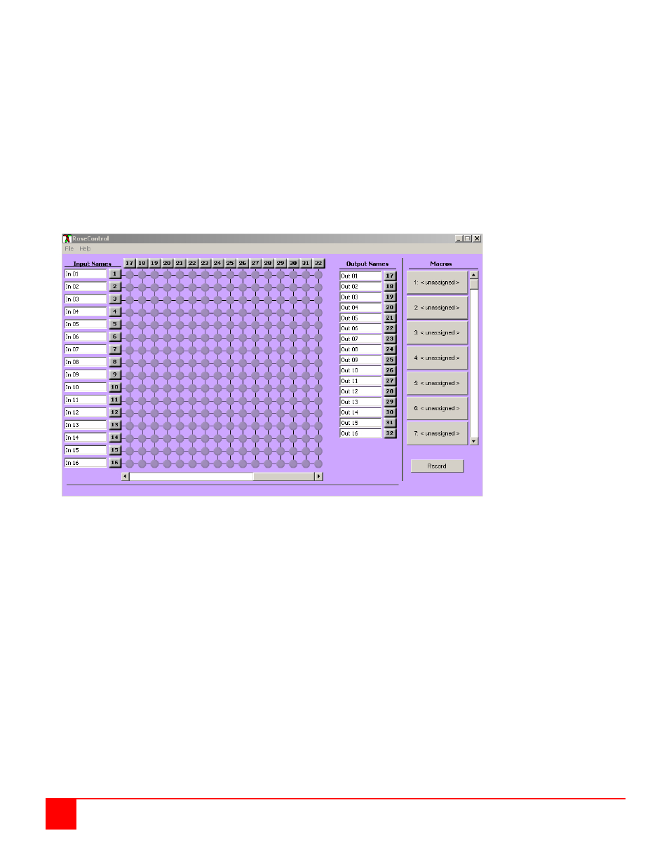
Figure 6. RoseControl 16x32
The RoseControl switching matrix will display a 16 in by 32 out matrix. Use the bottom scroll bar to display outputs 1-32.
Outputs 1-16 are the Master unit outputs and outputs 17-32 and the secondary unit outputs. To switch the input #1
video source to output #2 on the master and secondary units, click on the cross-point In 01, Out 02 and In01, Out 17.
This switches the video source on the master and secondary units to the input #1 port and the destination on the master
and secondary unit to output port #2.
This configuration routes a single video source to two output destinations, one on the master unit and one on the
secondary unit. The output destination pairs are 1 and 16, 2 and 17, 3 and 18, … 16 and 32. You can switch a single
video source to a single output port by not selecting the output port on the master (1-16) or the secondary (17-32) unit.