4 ignition system (ex27) – Subaru Robin EX13 User Manual
Page 53
- 50 -
7-4-3
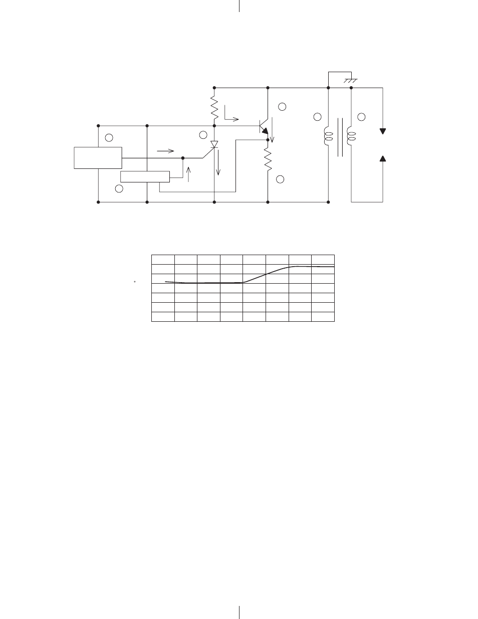
BASIC THEORY
(a) Revolution of the flywheel generates electricity on the primary side of the ignition coil (
), and the base
current I
1
flows to the power transistor (
). Current I
1
turns the power transistor “ON” and the electric
current I
2
flows. This is the same situation when the contact breaker is closed in a case of breaker point
type ignition system.
(b) At lower engine revolution, the low speed ignition timing control circuit (
) operates to run the gate
current I
3
to
turn the control thyristor (
) “ON”, thus the current I
1
bypass the thyristor as current I
5
.
At this moment, the power transistor (
) turns “OFF” and the current I
2
is shut off abruptly resulting
in the high voltage generated in the secondary coil (
) which produces sparks at the spark plug.
The ignition timing at lower engine revolution is less advanced as shown in the above chart.
(c) At higher engine revolution (over 2,000rpm), advancing control circuit (
) operates to run the gate current
I
4
to turn the control thyristor (
) “ON”, thus the current I
1
bypass the thyristor as current I
5
.
At this moment, the power transistor (
) turns “OFF” and the current I
2
is shut off abruptly resulting
in the high voltage generated in the secondary coil (
) which produces sparks at the spark plug.
At over 2,000rpm, ignition timing on each engine revolution is controlled by advancing control circuit (
)
that receive electrical information from revolution sensing resister (
).
The advancing of ignition timing from lower to higher engine revolution changes lineally as shown in
the above chart.
Fig.7-2b
7-4 IGNITION SYSTEM (EX27)
7-4-1
IGNITION COIL INTERNAL CIRCUIT
7-4-2
IGNITION TIMING CHARACTERISTIC
Fig.7-2a
3
4
0
0
500
1000
1500
2000
2500
3000
3500
4000
5
10
15
20
25
30
35
5
2
6
1
7
I
3
I
4
I
1
I
2
Low Speed Ignition
Timing Control
Circuit
Base Resister
Advancing Control
Circuit
Contr
ol th
yristor
I
5
Re
v
olution Sensing
Resister
P
o
wer T
ransistor
Primar
y Coil
Spark Plug
Secondar
y Coil
IGNITION TIMING
B.T.D.C.
( )
LINEAR ADVANCING
ENGINE REVOLUTION (R.P.M.)