Table 3. pattern generation, example 1 – KEPCO KLP Series (older -1200 models) VISA Driver Manual User Manual
Page 10
10
KLP-VISA 010906
2.2.9.9.1 The SINE, TRIANGLE and SQUARE waveform types are defined by the following parameters
(LEVEL is identical to DESTINATION of ALL, refer to PAR. 2.2.9.6):
•
Frequency (Hz) - Determines the dwell time of the waveform segment by 1/F (Hz) = Time (sec).
•
Start Angle (deg) - Integer from 0 to 360 - The starting point for the waveform segment (e.g., to
start a sine wave at max positive excursion, the start angle = 90, to start at max negative excur-
sion, start angle = 270).
•
End Angle (deg) - Integer from 0 to 360 - The ending point of the waveform segment. E.g., for a
negative half cycle of a sine wave, the start angle = 180, end angle = 360.
•
Amplitude (p-p) - The peak to peak amplitude of the complete waveform segment. E.g., if you
want a positive sine wave half cycle (start angle = 0, end angle = 180) from 0 to 15V, the p-p
amplitude for that segment must be set to 30V.
•
Waveform offset - The d-c level on which the waveform rides. If the negative excursion of the
waveform is used, the waveform offset must be sufficient to prevent the output from going below
zero, otherwise an error will result when Program RUN is attempted. E.g., if you want a full 15V
p-p sine wave cycle (start angle = 0, end angle = 360) from 10 to 25V, the p-p amplitude =15,
and the offset must be set to 17.5V (if the offset = 0 an error is produced when Program RUN is
attempted because the negative half cycle would require a negative voltage.
•
Current (If VOLTAGE destination) or Voltage (if CURRENT destination) - establishes the output
current for a voltage waveform, or the output voltage for a current waveform.
2.2.9.9.2 When the segment parameters have been entered, pressing the GENERATE button adds the
number of points specified in the Points window to the list. Note that, particularly in the case of the SINE
and TRIANGLE waveforms, the accuracy of the waveshape is affected by the number of points, e.g., a tri-
angle wave produced using 100 points will be close to a true triangle wave, while one produced using 5
points will resemble stair-steps.
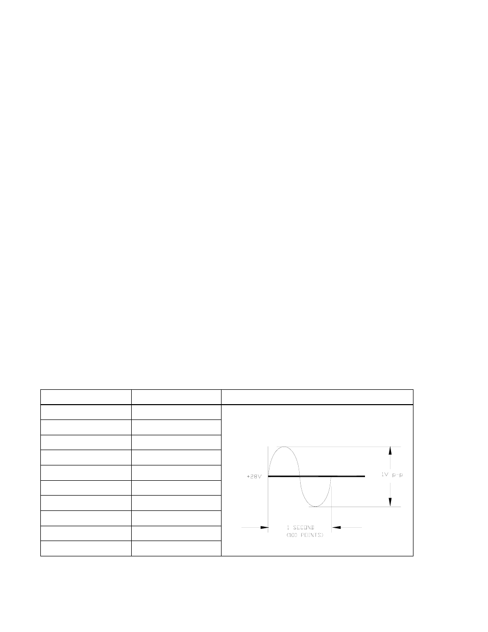
2.2.9.9.3 Pattern Generation, Example 1. To generate a single cycle of a voltage sine wave comprised
of one cycle with an amplitude of 1 volt peak to peak riding on a 28 volt level, a fixed current of 1 amp, with
relay off, and a total duration of 1 second, enter the parameters listed in Table 3.
TABLE 3. PATTERN GENERATION, EXAMPLE 1
PARAMETER
ENTER
RESULT
Destination
VOLTAGE
Press GENERATE button after all parameters entered to
add 100 points to list which will produce the following out-
put:
Waveform
SINE
Frequency (Hz)
1.000
Start Angle
0.000
End Angle
360.000
Amplitude (p-p)
1.000
Waveform Offset
28.000
Current
1.000
Relay
OFF
Points
100