Figure 2. main panel window, 2 main panel, Figure 3. protection window – KEPCO KLP Series (older -1200 models) VISA Driver Manual User Manual
Page 6
6
KLP-VISA 010906
. Once you are connected, you will see the Main Panel (Figure 2).
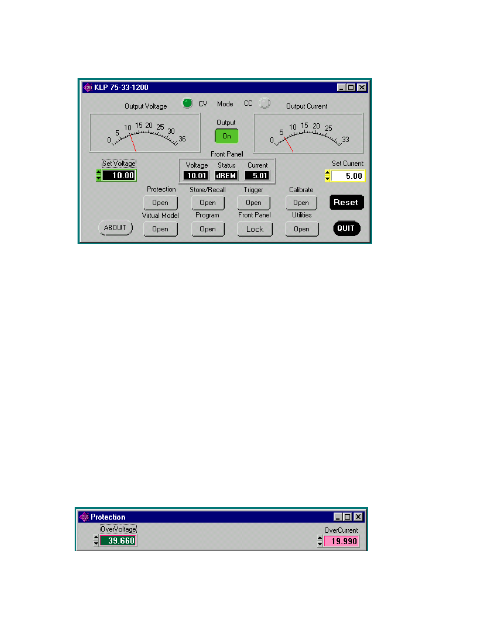
FIGURE 2. MAIN PANEL WINDOW
2.2 MAIN PANEL
The main panel window allows access to all power supply parameters without having to execute local con-
trols and read the corresponding display. The main panel is a real-time display of output values and pro-
grammed parameters. All functions are available from the main panel.
The operating mode (CV or CC) Mode indicators light to indicate whether the power supply is operating in
either CV (constant voltage) or CC (constant current) mode.
The analog meters read actual output voltage and current; Two windows beneath the meters are provided
to enter voltage and current setpoints. The Front Panel box shows a precise digital readout of the voltage
and current displayed on the analog meters (this is identical to the readouts on the KLP front panel DC
VOLTS and DC AMPERES displays) as well as showing messages appearing on the front panel Status
Display.
2.2.1 The Output button applies the programmed settings to the output terminals when set to ON or
keeps the output voltage at zero and current at minimum when set to OFF.
2.2.2 Set Voltage and Set Current windows are used to program the output voltage and current for the
unit; settings can be changed either by clicking on the arrows to the left of the display window, or by using
the mouse to highlight the setting, then typing in the new value.
2.2.3 The Protection button opens the Protection Window (Figure 3) which allows changing of the over-
voltage and overcurrent settings.
FIGURE 3. PROTECTION WINDOW