Figure 7. virtual model window, Figure 8. program lists window – KEPCO KLP Series (older -1200 models) VISA Driver Manual User Manual
Page 8
8
KLP-VISA 010906
2.2.7 The ABOUT button displays the model, serial number, firmware version number and driver version
number. Click OK to close the window
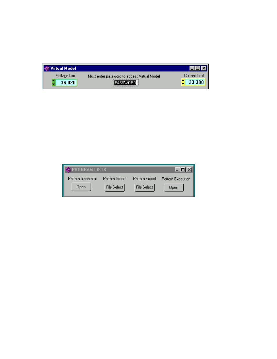
2.2.8 The Virtual Model button opens the Virtual Model window (Figure 7). The Password must be
entered, then the voltage and current limits for a virtual model can be set.
FIGURE 7. VIRTUAL MODEL WINDOW
2.2.9 Running or generating a program (pattern) is accomplished by clicking the Program button on the
Main Panel, opening the Program Lists window (Figure 8). Programs can either be defined point-by-point
using the Pattern Generator Open button, or by using the Pattern Import File Select button to import a
file containing the program parameters. Once the program is started, actual values of output current and
voltage are displayed. If you exit the program while the power supply is still on, the programmed settings in
effect at that time are maintained after exiting the program. Errors are discussed in PAR. 2.2.14.
2.2.9.1 The Pattern Generator Open button opens the Pattern Generation Window (Figure 10); the Pat-
tern Execution Open button opens the Pattern Execution window (Figure 11).
FIGURE 8. PROGRAM LISTS WINDOW
2.2.9.2 Patterns can be imported in comma-delineated text format using the Pattern Import File Select
button (Figure 8). The format, showing a single data point, is illustrated in Figure 9 and defined as follows:
2.2.9.3 The first line is a header, that defines columns (separated by commas) with a corresponding
parameter. The column with a “C” or “c” is defined as Current, “V” or “v” is defined as voltage, “D” or “d” is
defined as Dwell Time, and “Y” or “y“ is defined as Relay followed by (CR,LF). The second line defines the
first data point, with data separated by commas (in the same order as defined by the header), followed by
(CR,LF). Additional data lines define additional data points. The EOF defines the end of the pattern. A pat-
tern produced using the Pattern Generation window (Figure 10) can be saved in this format using the Pat-
tern Export File Select button.
FIGURE 9. FORMAT FOR TYPICAL COMMA-DELINEATED PATTERN GENERATION FILE
2.2.9.4 The Pattern Generation window (Figure 10) allows a user-specified program of up to 100 points to
be generated. This method of generating complex patterns, allows rigorous testing of a UUT (Unit Under
Test), within the boundaries determined by the virtual model and the load conditions.
Current,Voltage,Dwell,Relay(cr,lf)
1.0123E+02,3.600E+02,1.0E-02,0(cr,lf)
(eof)