Figure 10 pattern generation window, E 10) allo – KEPCO KLP Series (older -1200 models) VISA Driver Manual User Manual
Page 9
KLP-VISA 010906
9
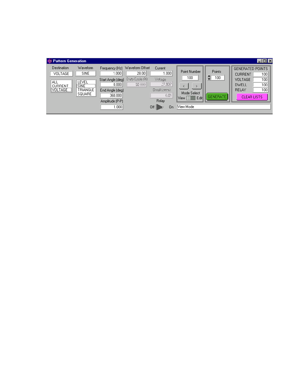
2.2.9.5 The GENERATED POINTS window shows the number of points currently included in the list for
each of the four parameters, CURRENT, VOLTAGE, DWELL and RELAY. The CLEAR LISTS button
clears all points in the list (individual points can be edited, but not deleted once they have been added).
FIGURE 10 PATTERN GENERATION WINDOW
2.2.9.6 There are three choices for DESTINATION: ALL, CURRENT or VOLTAGE.
• Destination of ALL means that all four parameters, CURRENT, VOLTAGE, DWELL and
RELAY must be entered for each point (RELAY is only available if the internal relay has
been set to PROGRAM mode). If a Virtual Model has been established, CURRENT and
VOLTAGE must be within the operating range of the Virtual Model, otherwise they must
be within the rated maximum values of the power supply. DWELL, the amount of time
that the programmed parameters will be in effect, can be set to any value from 0.01 to
655.36 seconds. RELAY ON (energized) or OFF (de-energized) controls the Normally
Open (I/O Connector, pin 2) and Normally Closed (I/O Connector, pin 10) contacts rela-
tive to Relay Common (I/O Connector, pin 4).
• Destination of CURRENT or VOLTAGE means that a waveform must be selected. The
four waveform choices are LEVEL, SINE, TRIANGLE and SQUARE. Waveforms may
consist of a single segment, or multiple segments, each defined separately (see PAR.
2.2.9.9 for details).
NOTE: The values chosen for Amplitude and Waveform Offset must be within the limits estab-
lished by the Protection and Virtual Model windows.
2.2.9.7 With the MODE SELECT switch set to VIEW, the parameters for each point can be viewed, but
not changed. The values displayed apply to the point indicated in the Point Number window. Use the
<
and
>
buttons to navigate through the list or enter a number directly in the Point Number window and
press ENTER on the computer keyboard to get to a specific point. By changing the MODE SELECT switch
to EDIT, values for existing points can be changed by entering a new value for any of the parameters.
2.2.9.8 As an example, if a five point list was to be entered, where all the values were the same except
the voltage, the list could be initially generated by specifying 5 points (which will all be identical), then set-
ting the MODE SELECT switch to EDIT and using the
<
and
>
buttons to view and edit the voltage for
each point
2.2.9.9 Complex Pattern Generation. When the Destination is set to CURRENT or VOLTAGE, the pat-
tern generator window (Figure 10) can be used to produce a complex waveform. The complex output is
built by adding segments from each of the four basic waveform types: LEVEL, SINE, TRIANGLE or
SQUARE. Each time the GENERATE button is clicked, the waveform selected is generated using the
number of points specified in the Points Window. Setting Destination set to CURRENT produces a cur-
rent waveform; a Destination of VOLTAGE produces a voltage waveform.