Input/output pin assignments for remote control -4 – KEPCO MBT Series User Manual
Page 28
2-4
MBTSVC 111609
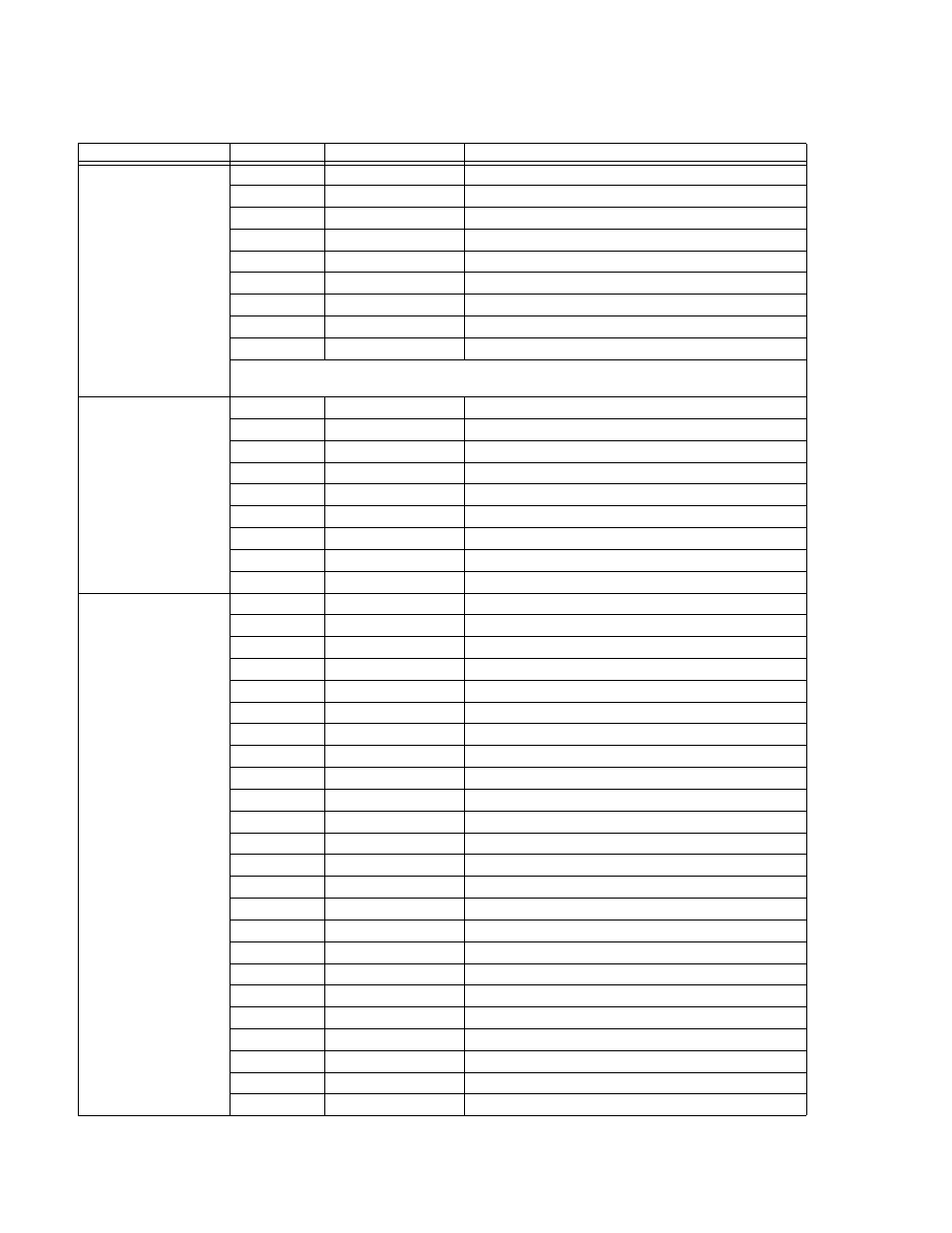
TABLE 2-2. INPUT/OUTPUT PIN ASSIGNMENTS FOR REMOTE CONTROL
CONNECTOR
PIN
SIGNAL NAME
FUNCTION
RS232-C
J4
1
SGND
Signal Ground
2
RXD
Receive Data
3
TXD
Transmit Data
4
DTR
( not used)
5
SGND
Signal Ground
6
DSR
See Note.
7
RTS
See Note.
8
CTS
Clear To Send (protocol not used)
9
SGND
Signal Ground
NOTE: Jumper installed beteen DSR and RTS allows secondary GPIB addressing if SCPI mode (see
Table 2-4) is selected
IEEE 1118
INPUT/OUTPUT
J2, J3
1
Not used
2
SHIELD
Shield
3
IEEE 1118 BUS
Communicate via IEEE 1118 bus
4
Not used
5
Not used
6
Not used
7
SHIELD
Shield
8
IEEE 1118 BUS
Communicate via IEEE 1118 bus
9
Not used
IEEE 488
PORT
J5
1
D
I
01
I/O Line
2
D
I
02
I/O Line
3
D
I
03
I/O Line
4
D
I
04
I/O Line
5
EOI
End or Identify
6
DAV
Data Valid
7
NRFD
Not Ready for Data
8
NDAC
Not Data Accepted
9
IFC
Interface Clear
10
SRQ
Service Request
11
ATN
Attention
12
SHIELD
Shield
13
D
I
05
I/O Line
14
D
I
06
I/O Line
15
D
I
07
I/O Line
16
D
I
08
I/O Line
17
REN
Remote Enable
18
GND
Ground (signal common)
19
GND
Ground (signal common)
20
GND
Ground (signal common)
21
GND
Ground (signal common)
22
GND
Ground (signal common)
23
GND
Ground (signal common)
24
LOGIC GND
Logic Ground