Whelen IONJ User Manual
Whelen For the car
For warranty information regarding this product, visit
www.whelen.com/warranty
©2010 Whelen Engineering Company Inc.
Form No. 14436D (061411)
®
ENGINEERING COMPANY INC.
51 Winthrop Road,
Chester, Connecticut 06412-0684
Phone: (860) 526-9504
Fax: (860) 526-4078
Sales Email:[email protected]
Canadian Sales:[email protected]
Customer Service:[email protected]
www.
.com
ION™ Light (Split)
Operation
Scan-Lock™(WHT/VIO) - To advance to the next pattern
To cycle backwards
To reset to the factory default
pattern
Sync (GREY) -
IMPORTANT!
simultaneously
alternate
, apply +VDC to the WHT/VIO wire for less
than 1 second.
, apply +VDC for more than 1 second.
, turn off power to the lighthead. While applying +VDC to the WHT/VIO, turn the lighthead back on.
Continue to apply voltage for 5 seconds.
Lightheads configured to display the Phase 1 mode of a pattern will flash simultaneously. Any lightheads
configured to display the Phase 2 mode will alternate with any Phase 1 lightheads with the same pattern.
To sync two lightheads, configure both lightheads to display the same Phase 1 pattern.
With the power off, connect the GREY wires from each lighthead together. When the lightheads are
activated, their patterns will be synchronized. To configure the two lightheads to alternate their patterns,
advance the pattern of either lighthead to the Phase 2 mode of the current pattern. The same concept
applies to Phases 3 & 4.
To understand how to use the sync feature with more than two lightheads, the principles will be applied to a
sample system consisting of 4 lightheads with 2 mounted on the rear, driver-side and 2 mounted on the
rear, passenger-side. With all the wiring complete, turn on all 4 lightheads. As shipped from factory, the
lightheads will all display SignalAlert™ 75 - Phase 1. To configure one side to alternate with the other side,
change the pattern for either the passenger or driver side to Phase 2 mode for that pattern.
SYNC-capable LED lightheads can be SYNCed to a SYNC-capable strobe power supply
(such as the CS240S or UPS64LXA) by wiring their GREY wires together. When connected, LED
lightheads in Phase 1 of a pattern will flash
with strobe lightheads connected to the
GREEN wire outputs. LED lightheads set to Phase 2 of a pattern will
with strobe lightheads
connected to the WHITE wire outputs. GREEN wire outputs always alternate with WHITE wire outputs.
W
G
B
HT / VIO
RY
LK
RED/WHT (2-color Split)
WHT/RED (1-color Split)
or
Scan-Lock™
SYNC
Switch*
(SP/ST)
Fuse*
(3 AMP)
*Customer Supplied
(+)
12V Battery
(-)
Flash Patterns:
BOLD
.
/
NOTE:
= CA Title XIII Compliant Pattern
= SYNC Pattern
Italic
/ PH 1 = Phase 1, PH 2 = Phase 2
1. SignalAlert™ 75 (PH 1)
2. SignalAlert 75 (PH 2)
3. SignalAlert 75 (PH 3)
4. SignalAlert 75 (PH 4)
5. CometFlash® 75 (PH 1)
6. CometFlash 75 (PH 2)
7. CometFlash 75 (PH 3)
8. CometFlash 75 (PH 4)
17. ComAlert™ 75 (PH 1)
18. ComAlert 75 (PH 2)
19. ComAlert 75 (PH 3)
20. ComAlert 75 (PH 4)
21. LongBurst™ 75 (PH 1)
22. LongBurst 75 (PH 2)
23. LongBurst 75 (PH 3)
9. DoubleFlash 75 (PH 1)
10. DoubleFlash 75 (PH 2)
11. DoubleFlash 75 (PH 3)
12. DoubleFlash 75 (PH 4)
13. SingleFlash 75 (PH 1)
14. SingleFlash 75 (PH 2)
15. SingleFlash 75 (PH 3)
16. SingleFlash 75 (PH 4)
24. LongBurst 75 (PH 4)
29. SSNF 75 (PH 1)
30. SSNF 75 (PH 2)
25. PingPong™ 75 (PH 1)
26. PingPong 75 (PH 2)
27. PingPong 75 (PH 3)
28. PingPong 75 (PH 4)
31. SingleFlash 60 (Alt.)
32. SingleFlash 60 (Sim.)
SingleFlash
(
SingleFlash 0 (Sim.)
35. SingleFlash 120 (Alt.)
36. SingleFlash 120 (Sim.)
SingleFlash 300 (Alt.)
38. SingleFlash 300 (Sim.)
DoubleFlash 150 (Alt.)
40. DoubleFlash 150 (Sim.)
41. ComAlert™ 150 (Alt.)
42. ComAlert™ 150 (Sim.)
43. ActionFlash™ 50 (Alt.)
44. ActionFlash™ 50 (Sim.)
45. ActionFlash™ 150 (Alt.)
46. ActionFlash™ 150 (Sim.)
33.
90 Alt.)
34.
9
37.
39.
47. ModuFlash™ (Alt.)
48. ModuFlash™ (Sim.)
64. ActionScan™ (Alt./Sim.)
49. DoubleFlash 120 (Alt.)
50. DoubleFlash 120 (Sim.)
51. PingPong™ 120 (Alt.)
52. PingPong 120 (Sim.)
53. TripleFlash™ 75 (Alt.)
54. TripleFlash 75 (Sim.)
55. TripleFlash 120 (Alt.)
56. TripleFlash 120 (Sim.)
57. SigAlert Cal.™ (Alt.)
58. SigAlert Cal. (Sim.)
59. Action SF 60/120 (Alt.)
60. Action SF 60/120 (Sim).
61. Action SF60/TF120 (Alt.)
62. Action SF60/TF120 (Sim.)
63. CalScan™ (Alt./Sim.)
65. SteadyFlash 60
66. SteadyFlash 75
67. SteadyFlash 90
68. SteadyFlash 120
69. Steady & Steady
ON
OFF
ON
Split Lighthead Operation:
PHASE 1 - LEFT
RIGHT
side
with
side.
alternates
PHASE 2 - RIGHT
LEFT
side
with
side.
alternates
PHASE 3 - BOTH sides flash
together (ON-OFF-ON).
PHASE 4 - BOTH sides flash
together (OFF-ON-OFF).
Phases 3 & 4 are visually indistinguishable.
OFF
OFF
ON
OFF
ON
ON
OFF
ON
OFF
ON ON
OFF OFF
OFF OFF
ON
ON
ON
ON
OFF OFF
IMPORTANT! It is the responsibility of the installation technician to make sure that the installation
and operation of this product will not interfere or compromise the operation or efficiency of any
vehicle equipment!
Before returning the vehicle to active service, visually confirm the proper operation of this product,
as well as all vehicle components and/or equipment.
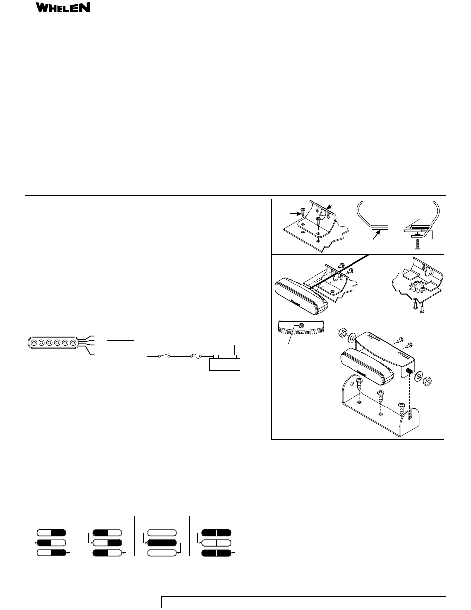
Mounting (Standard Bracket)
NOTE:
Wiring
1. Place the bracket against the mounting surface and mark the two mounting hole locations.
2. Drill two mounting holes sized for a #8 sheet metal screw. A wire passage hole may also be needed. De-burr this
hole and install a grommet to protect the wires.
If VHB tape (provided) is used, remove the protective backing from this tape and press it firmly onto the bottom
of the bracket as shown. Clean the mounting surface with a 50/50 mix of isopropyl alcohol and water and dry thoroughly
before mounting the bracket onto the mounting surface.
3. Route the wires through the hole in the bracket and through the wire passage hole. Secure the ION™ to the bracket
using the hardware provided. Wire as outlined below.
Mounting (Gripper Bracket)
Mounting (Bail Bracket)
1. Apply the protective pads to the bracket in the location shown (side view). Secure the ION™ to the bracket in
the same fashion as outlined for the standard bracket.
2. Position the bracket onto the proposed mounting surface as shown. Apply a drop of Loctite 222 to the threads
of the #6 x ½" PPHMS provided.
3. Thread these screws into the underside of the bracket as shown and secure the bracket to the mounting
surface.
1. Secure the bail bracket to the desired surface using the hardware provided. Mount the ION onto the shield
bracket and install this assembly onto the bail bracket as shown.
Safety First
This document provides necessary information to allow your Whelen product to be properly and safely installed. Before beginning the installation and/or operation of this
product, the installation technician and operator must read this manual completely. Important information is contained herein that could prevent serious injury or damage.
!
!
!
!
!
Proper installation of this product requires the installer to have a good understanding of
automotive electronics, systems and procedures.
Failure to use specified installation parts and/or hardware will void the product warranty!
The installer MUST be sure that no vehicle components or other vital parts could be
damaged by the drilling process. Check both sides of the mounting surface before drilling
begins. Also de-burr any holes and remove any metal shards or remnants. Install
grommets into all wire passage holes.
Do not install this product or route any wires in the deployment area of your air bag.
Equipment mounted or located in the air bag deployment area will damage or reduce the
effectiveness of the air bag, or become a projectile that could cause serious personal injury
or death. Refer to your vehicle owner's manual for the air bag deployment area. The
User/Installer assumes full responsibility to determine proper mounting location, based on
providing ultimate safety to all passengers inside the vehicle.
If this product uses a remote device to activate or control this product, make sure that this
control is located in an area that allows both the vehicle and the control to be operated
safely in any driving condition.
!
!
!
!
!
Do not attempt to activate or control this device in a hazardous driving situation.
This product contains high-intensity LEDs. Do not stare directly into these lights.
Momentary blindness and/or eye damage could result.
Use only soap and water to clean the outer lens. Use of other chemicals could result in
premature lens cracking (crazing) and discoloration. Lenses in this condition have
significantly reduced effectiveness and should be replaced immediately. Inspect and
operate this product regularly to confirm its proper operation and mounting condition.
Do not use a pressure washer to clean this product.
WARNING! All customer supplied wires that connect to the positive (+) terminal of the
battery must be sized to supply at least 125% of the maximum operating current and
FUSED “at the battery” to carry that load. DO NOT USE CIRCUIT BREAKERS WITH THIS
PRODUCT!
Failure to follow these precautions and instructions could result in damage to the
product or vehicle and/or serious injury to you and your passengers!
#8 x 1/2
Sheet Metal
Screw
Mounting
Bracket
#6-32 x 5/16
Screw
#6-32 x 1/2
Screw
Cable
VHB Tape
(optional)
Standard
Bracket
Gripper
Bracket
Standard
Bracket
(side view)
Protective
Pad
Mounting
Surface
Gripper Bracket
(side view)
IMPORTANT!
The membrane shown must
always face downwards!
Do not cover, obstruct or
remove this membrane
regardless of mounting style!
#6-32 x 5/16
Screw
1/4-20 Elastic
Stop Nut
Flat
Washer
#10 x 1/2
PPHSMS
Shield
Bracket
Bail
Bracket
- IOND IONM IONWJ IONWD IONWM WIONJ WIOND WIONM WIONWJ WIONWD IONA IONWA WIONA WIONWA IONG IONV3A IONV3AW 3SC0CDCR 3SA00FAR 3SBCCDCR 3SRCCDCR 3SR0CDRR IONV1A IONV1AW PAR28DA PAR28DJ UFM8 20C0CDCR 20C0CDCD SFIOND SFIONJ SFIONE SFP1A SFP1G SFP1J SFP1E SFP1D IONSMJ IONSMD IONSMM IONSMWJ IONSMWD IONSMWM WIONSMJ WIONSMD WIONSMM WIONSMWJ WIONSMWD WIONSMWM WIONSMCD RSA02ZCR RSA03ZCR RVA03ZCR RSC02ZCR RSC03ZCR RVC03ZCR RSG02ZCR RSG03ZCR LINZ6K LINZ6J LINZ6D LINZ61 LINZ62 LINZ65 LINZ6A LINZ6A24 LINZ6G IONSMA IONSMWA IONSMCA WIONSMA WIONSMWA WIONSMCA