Whelen SFP1A User Manual
Whelen For the car
For warranty information regarding this product, visit
www.whelen.com/warranty
©2008 Whelen Engineering Company Inc.
Form No. 14206 (062308)
®
ENGINEERING COMPANY INC.
Route 145, Winthrop Road,
Chester, Connecticut 06412
Phone: (860) 526-9504
Fax: (860) 526-4078
Sales Email:[email protected]
Canadian Sales:[email protected]
Customer Service:[email protected]
www.
.com
SpitFire™ LED Dash Light
Safety First
This document provides all the necessary information to allow your Whelen product to be properly and safely installed. Before beginning the installation
and/or operation of your new product, the installation technician and operator must read this manual completely. Important information is contained herein
that could prevent serious injury or damage.
!
!
!
!
!
Proper installation of this product requires the installer to have a good
understanding of automotive electronics, systems and procedures.
If mounting this product requires drilling holes, the installer MUST
be sure that no vehicle components or other vital parts could be
damaged by the drilling process. Check both sides of the mounting
surface before drilling begins. Also de-burr any holes and remove any
metal shards or remnants. Install grommets into all wire passage holes.
Do not install this product or route any wires in the deployment
area of your air bag. Equipment mounted or located in the air bag
deployment area will damage or reduce the effectiveness of the air bag,
or become a projectile that could cause serious personal
injury or death. Refer to your vehicle owners manual for the air bag
deployment area. The User/Installer assumes full responsibility to
determine proper mounting location, based on providing ultimate
safety to all passengers inside the vehicle.
For this product to operate at optimum efficiency, a good electrical
connection to chassis ground must be made. The recommended
procedure requires the product ground wire to be connected
directly to the NEGATIVE (-) battery post.
If this product uses a remote device to activate or control this product,
make sure that this control is located in an area that allows both the
vehicle and the control to be operated safely in any driving condition.
!
!
!
!
!
Do not attempt to activate or control this device in a hazardous
driving situation.
This product contains either strobe light(s), halogen light(s),
high-intensity LEDs or a combination of these lights. Do not stare
directly into these lights. Momentary blindness and/or eye damage
could result.
Use only soap and water to clean the outer lens. Use of other chemicals
could result in premature lens cracking (crazing) and discoloration.
Lenses in this condition have significantly reduced effectiveness
and should be replaced immediately. Inspect and operate this product
regularly to confirm its proper operation and mounting condition. Do
not use a pressure washer to clean this product.
FAILURE TO FOLLOW THESE PRECAUTIONS AND INSTRUCTIONS
COULD RESULT IN DAMAGE TO THE PRODUCT OR VEHICLE AND/OR
SERIOUS INJURY TO YOUAND YOUR PASSENGERS!
WARNING! All customer supplied wires that connect to the positive (+)
terminal of the battery must be sized to supply at least 125% of the
maximum operating current and
“at the battery” to carry that
load. DO NOT USE CIRCUIT BREAKERS WITH THIS PRODUCT!
FUSED
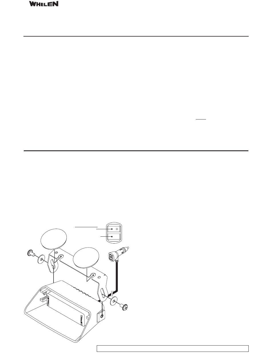
CAUTION! This product has been designed to rest on top of the vehicle's
dashboard. Suction cups are provided to prevent lateral movement while
the vehicle is in motion. These suction cups should not be used to
suspend this product above the dashboard. Clean suction cup mounting
surface thoroughly before mounting.
IMPORTANT! It is the responsibility of the installation technician to make
sure that the installation and operation of this product will not interfere
with or compromise the operation or efficiency of any vehicle equipment!
IMPORTANT! The light output of this product should be projected parallel
to the road.
TO CYCLE FORWARD, press the Scan-Lock™ button for less than 1
second and release.
TO CYCLE BACKWARDS, press the
button for more than 1
second and release.
TO RESTORE FACTORY DEFAULT, turn the power to the unit off. Press
and hold the
button while turning the power on. Allow this
pattern to run for at least 5 seconds to complete the selection.
Scan-Lock™
Scan-Lock™
NOTE: The cigar cord adaptor is equipped
with an 8 Amp Fuse. If the fuse must ever
be replaced, be sure to use one with an
identical value.
Switch Functions
SW1 - ON/OFF
SW2 - Scan-Lock™
1. SignalAlert™75 - ALT 1
2. SignalAlert™75 - ALT 2
3. SignalAlert™75 - SIM 1
4. SignalAlert™75 - SIM 2
5. CometFlash®75 - ALT 1
6. CometFlash®75 - ALT 2
7. CometFlash®75 - SIM 1
8. CometFlash®75 - SIM 2
9. DoubleFlash 75 - ALT 1
10. DoubleFlash 75 - ALT 2
11. DoubleFlash 75 - SIM 1
12. DoubleFlash 75 - SIM 2
13. SingleFlash 75 - ALT 1
14. SingleFlash 75 - ALT 2
15. SingleFlash 75 - SIM 1
16. SingleFlash 75 - SIM 2
17. ComAlert™75 - ALT 1
18. ComAlert™75 - ALT 2
19. ComAlert™75 - SIM 1
20. ComAlert™75 - SIM 2
21. LongBurst™75 - ALT 1
22. LongBurst™75 - ALT 2
23. LongBurst™75 - SIM 1
24. LongBurst™75 - SIM 2
25. PingPong 75 - ALT 1
26. PingPong 75 - ALT 2
27. PingPong 75 - SIM 1
28. PingPong 75 - SIM 2
29. SSNF 75 - ALT
30. SSNF 75 - SIM
31. SingleFlash 60 - ALT
32. SingleFlash 60 - SIM
SingleFlash
-
SingleFlash 0 - SIM
35. SingleFlash 120 - ALT
33.
90 ALT
34.
9
36. SingleFlash 120 - SIM
SingleFlash 300 - ALT
38. SingleFlash 300 - SIM
DoubleFlash 150 - ALT
40. DoubleFlash 150 - SIM
41. ComAlert™ 150 - ALT
42. ComAlert™ 150 - SIM
43. ActionFlash™ 50 - ALT
44. ActionFlash™ 50 - SIM
45. ActionFlash™150 - ALT
46. ActionFlash™150 - SIM
47. ModuFlash™ - ALT
48. ModuFlash™ - SIM
49. DoubleFlash 120 - ALT
50. DoubleFlash 120 - SIM
51. PingPong™ 120 - ALT
52. PingPong™ 120 - SIM
53. TripleFlash 75 - ALT
54. TripleFlash 75 - SIM
55. TripleFlash 120 - ALT
56. TripleFlash 120 - SIM
57. SigAlert Cal.™ - ALT
58. SigAlert Cal.™ - SIM
59. Action SF 60/120 - ALT
60. Action SF 60/120 - SIM
61. Action SF60/TF120 - ALT
62. Action SF60/TF120 - SIM
63. CalScan™ - ALT/SIM
64. ActionScan™ - ALT/SIM
65. SteadyFlash 60
66. SteadyFlash 75
67. SteadyFlash 90
68. SteadyFlash 120
69. Steady & Steady
37.
39.
Scan-Lock™ Patterns:
ALT = Alternating
SIM = Simultaneous
- SFP1G SFP1J SFP1E SFP1D SFIOND SFIONJ SFIONE SFIONA R1A R2AA TADP6 TADP8 TADP8AA TAD6 TAD8 TAD8AA DP2AA DP4AAAA 3SC0CDCR 3SA00FAR 3SBCCDCR 3SRCCDCR 3SR0CDRR IONV1A IONV1AW IONA IONWA WIONA WIONWA IONWD IONG IONJ IOND IONM IONWJ IONWM WIONJ WIOND WIONM WIONWJ WIONWD IONV3A IONV3AW PAR28DA PAR28DJ UFM8 20C0CDCR 20C0CDCD AVN1A AVN1J AVN2AA AVNS1A AVNS2AA AVNBKT1 AVNBKT2 AVNBKT3 AVNBKT4 FLLEDAA RB6TAP D2AA D4AAAA D6AAAAAA 580CAAAR 580CAAZR 60C0EJCS 60U0EJCS