Whelen PEIMDC12 User Manual
Miscellaneous, Rear view (to aftermarket police equipment), Rear view (to dodge charger interface module)
Page 1
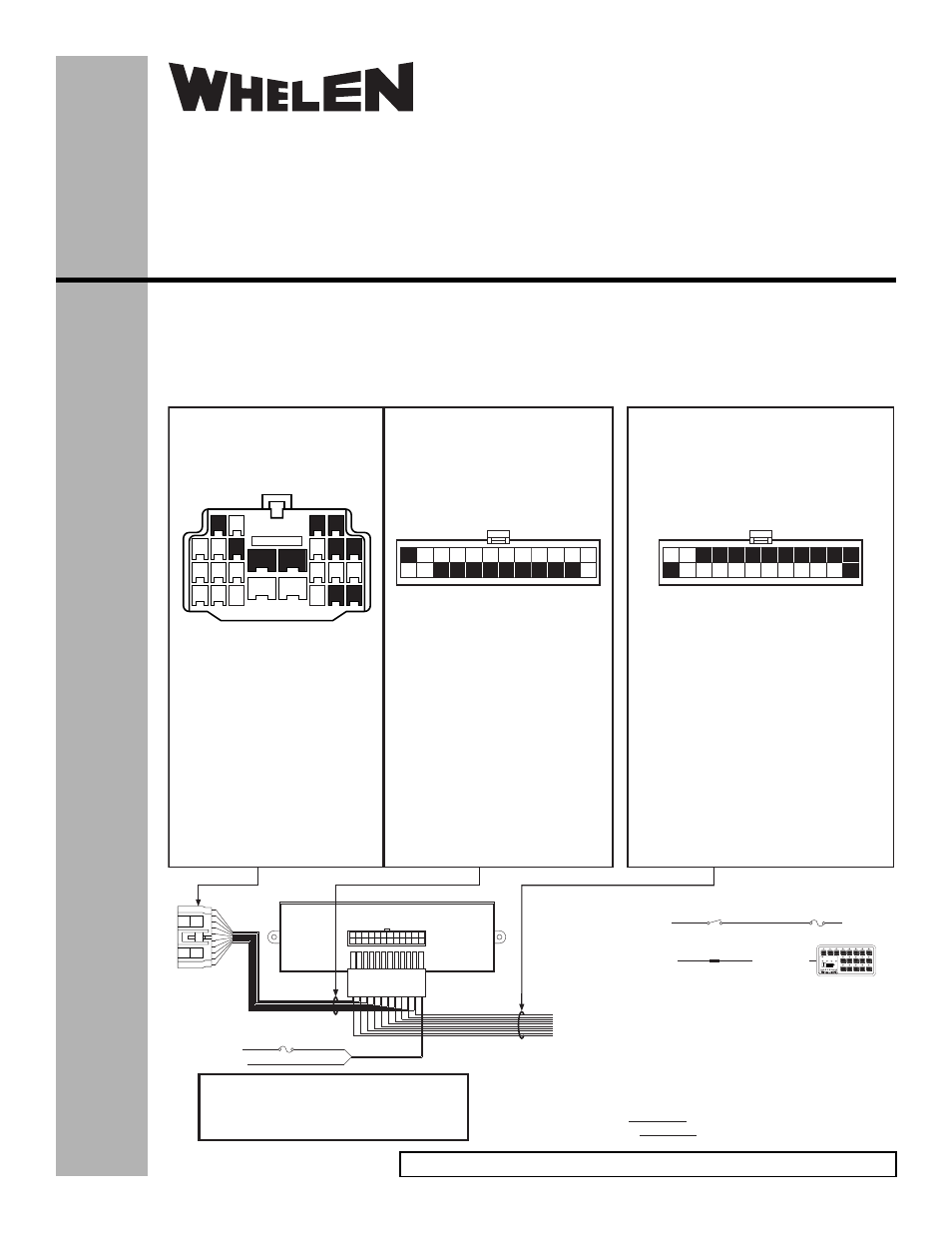
POS 1 -
POS 2 - Input / WHT/RED (HORN MUTE)*
POS 3 - Input / BRN (FRONT WIG WAGS)
POS 4 - Input / RED (6”) (REAR WIG WAGS)*
POS 13 - BLK (10”) (GROUND)
RED (10”) (+12VDC) Fuse @ 5A
*
POS 5 - Output / BLK/WHT (HORN SWITCH ACTIVATED)*
POS 6 - Output / WHT/GRY (PARK)*
POS 7 - Output / WHT/BLK (BRAKE)*
POS 8 - Output / BLU/BLK (ENGINE RUNNING)*
POS 9 - Output / WHT/GRN (DRIVER SIDE AJAR)*
POS 10 - Output / WHT/YEL (HEADLIGHT)*
POS 24 - Output / WHT/VIO (VEHICLE SPEED)****
*
**
*
*
*
*
REAR VIEW
(to aftermarket
police equipment)
POS 12 - WHT/VIO (VEHICLE SPEED)
POS 14 -
POS 15 - BRN (FRONT WIG-WAGS)
POS 16 - RED (REAR WIG WAGS)
POS 17 - BLK/WHT (HORN SWITCH ACTIVATED)
POS 18 - WHT/GRY (PARK)
POS 19 - WHT/BLK (BRAKE)
POS 20 - BLU/BLK (ENGINE RUNNING)
POS 21 - WHT/GRN (DRIVER DOOR AJAR)
POS 22 - WHT/YEL (HEADLIGHT)
WHT/RED (HORN MUTE)
REAR VIEW
(to Dodge Charger
Interface Module)
PIN 1 - BRN (FRONT WIG-WAGS)
PIN 2 - RED (REAR WIG-WAGS)
PIN 4 - WHT/BLK (BRAKE)
PIN 5 - BLK/WHT (HORN SWITCH ACTIVATED)
PIN 6 - WHT/GRY (PARK)
PIN 8 - WHT/YEL (HEADLIGHT)
PIN 14 - BLU/BLK (ENGINE RUNNING)
PIN 15 - WHT/GRN (DRIVER DOOR AJAR)
PIN 19 - WHT/VIO (VEHICLE SPEED)
PIN 20 - WHT/RED (HORN MUTE)
REAR VIEW
(to Police Equipment
Interface Connector)
*Inputs require a 0.25ma signal MIN (12VDC)
**Outputs are rated for 13ma@12VDC MAX
***+12V in Drive, Ground in Park
****Analog output:1V per 10 m.p.h.
Sample Connections
5A Fuse
(Customer Supplied)
1A Fuse
SP/ST Switch
RED (To +12VDC)
BRN (front wig-wags) - Input
+12VDC
BLACK (To Ground)
WARNING! All customer supplied wires that connect to
the positive terminal of the battery must be sized to
supply at least 125% of the maximum operating
current and FUSED at the battery to carry that load. DO
NOT USE CIRCUIT BREAKERS WITH THIS PRODUCT!
In the above configuration, the front wig-wags
are activated with the SP/ST switch shown.
Also, when the vehicle headlights are turned on,
the headlight output wire (WHT/YEL) will provide
+12VDC to the backlight wire of the sample
control head.
Remember:
Inputs
+12VDC
Outputs
+12VDC
REQUIRE
PROVIDE
Butt Splice
WHT/YEL (headlight) - Output
YEL (backlight)
1
2
3
STAND
BY
RAD
PA
T3
MAN
HF
WAIL
YELP
VOL.
UP
VOL.
DOWN
9
(LOW
POWER)
MANUAL
(MOM.)
AIR
HORN
(MOM.)
SW4
SW5
SW6
SW7
SW8
(T/A)
14
15
16
17
18
19
20
21
11
12
22
23
1
13
2
3
4
5
6
7
8
9
10
24
1
13
2
3
4
5
6
7
8
9
10
23
24
14
15
16
17
18
19
20
21
22
11
12
16
11
9
17
12
23
10
7
18
13
24
21
22
2
1
3
5
6
8
14
15
19
20
4
®
ENGINEERING COMPANY INC.
51 Winthrop Road
Chester, Connecticut 06412-0684
Phone: (860) 526-9504
Fax: (860) 526-4078
Internet: www.whelen.com
Sales e-mail: [email protected]
Miscellaneous
Installation Guide:
Police Equipment Upfitter
Interface Module
(2012 Dodge Charger)
©2012 Whelen Engineering Company Inc.
Form No.14658A (073013)
This module provides conditioned signals to and from the
Police Equipment Interface Module (PEIM) found on all
Dodge Charger police vehicles. The 24-position PEIM
connector is located under the Instrument Panel Center
Console. To access this connector, it is necessary to
remove the plastic cover located just ahead of the police
equipment mounting bracket on the center console. For
further information, refer to the Police Package Owner’s
Manual supplied with the vehicle.
WARNING! Do not alter the vehicle harness circuits
in any manner (including splicing or cutting).
For warranty information regarding this product, visit www.whelen.com/warranty