Whelen UFM8 User Manual
Automotive: flashers, Installation guide: ufm8 universal flasher
Page 1
Installation Guide:
UFM8 Universal Flasher
©1999 Whelen Engineering Company Inc.
Form No.13496A (121499)
This UFM8 Universal Flasher, like all Whelen components,
can be installed in many different types of vehicles. The
guidelines for the installation of this product are written so
that no matter what vehicle is being used, the installation and
operation of the unit will be simple and straight forward.
Selecting a Mounting Location:
The most common choice for a mounting area would be a
trunk or similar compartment. However, due to the wide
variety of vehicles onto which the unit could be installed, this
is not always possible. The following guidelines will help the
installer select an acceptable alternative:
A)
The flasher should be mounted on a metal surface to aid
heat dissipation. Be sure that this surface is not one that
either generates or is exposed to excessive heat during
normal operation of the vehicle.
B)
Do not select a location where the unit will be exposed
to potential damage from any unsecured or loose equip-
ment in the vehicle.
C)
Be sure the area selected will not allow the unit to be
exposed to water.
D)
When routing wires, it is important to choose a path that
will keep these wires away from excessive heat and
from any vehicle equipment that could compromise the
integrity of the wires (ex. trunk lids, door jams, etc..)
E)
When the best mounting location has been determined,
securely fasten the unit to it’s mounting surface.
CAUTION: As it will be necessary to drill holes into the
mounting surface, the installer MUST be sure that no
vehicle components or other vital parts could be
damaged by the drilling process. Check both sides of the
mounting surface before drilling begins.
Mounting your UFM8:
1.
Position the UFM8 in its proposed mounting location to
ensure that it fits properly. With the unit in place, insert
an awl or other suitable tool into the mounting screw
area of the flasher and scribe the areas to be drilled.
2.
Remove the unit from its mounting area and, using a
drill bit sized for a #8 sheet metal screw, drill a hole in
each of the areas scribed in the previous step.
3.
Return the UFM8 to its mounting location and using the
supplied #8 sheet metal screws, mount the unit .
Wiring your UFM8:
1.
Locate the 4 position Input Connector included with your UFM8
and plug it into the port indicated on page 2. Run the 2 BLACK
wires and the 2 RED wires to the battery.
WARNING: All customer supplied wires, that connect to the positive (+)
terminal of the battery, must be sized to supply at least 125% of the
maximum operating current, and fused “at the battery” to carry the load.
2.
Connect the RED wires to a fuse block (customer supplied) and
then to the POSITIVE terminal on the battery.
NOTE! Although a fuse (customer supplied) is required to be used in
the fuse block, do not install the fuse until all wire connections are com-
pleted.
3.
Connect the BLACK wires to the factory chassis ground adjacent
to the battery.
4.
Refer to diagram on page 2 for wiring information for the remaining
Switch Control Wires and Pattern Control Wires.
Control Wires:
In this configuration, applying +12VDC to the control wires (using
customer supplied switches) will have the following results:
Control Wire #1 = Outlets 1 & 2 Enabled
Control Wire #2 = Outlets 3 & 4 Enabled
Control Wire #3 = Outlets 5 & 6 Enabled
Control Wire #4 = Outlets 7 & 8 Enabled
Pattern Control: The factory pre-set default pattern is RapidFire
™
240.
(see Available Flash Patterns Pg. 2.)
To cycle up through all the available flash patterns, activate the pattern
control switch momentarily, (less than one second) and release. After 5
seconds of operation, the pattern selected is now the default pattern
and will remain so until another pattern is selected. To cycle backwards
through the available patterns, activate the pattern control switch for
more than one second and release.
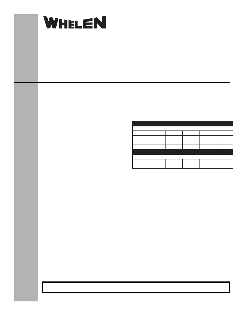
INPUT POWER AND GROUND / MAXIMUM WIRE LENGTH (Ft.)
Wire Gauge / AWG
Input Fuse
7.5 AMPS
18 AWG 16 AWG 14 AWG 12 AWG 10 AWG
10 FT
16 FT
27 FT
42 FT
67 FT
15 AMPS
5 FT
8 FT
13 FT
21 FT
33 FT
25 AMPS
N/A
5 FT
8 FT
13 FT
20 FT
Wire Gauge / AWG
Input Fuse
3 AMPS
22 AWG 18 AWG 16 AWG
10 FT
26 FT
42 FT
CONTROL WIRES / MAXIMUM WIRE LENGTH (Ft.)
®
ENGINEERING COMPANY INC.
51 Winthrop Road
Chester, Connecticut 06412-0684
Phone: (860) 526-9504
Fax: (860) 526-4078
Internet: www.whelen.com
Sales e-mail: [email protected]
Canadian Sales e-mail: [email protected]
Customer Service e-mail: [email protected]
Automotive:
Flashers
For warranty information regarding this product, visit www.whelen.com/warranty