Kit components – Amprobe AT-7000 User Manual
Page 10
6
2. Kit comPonents
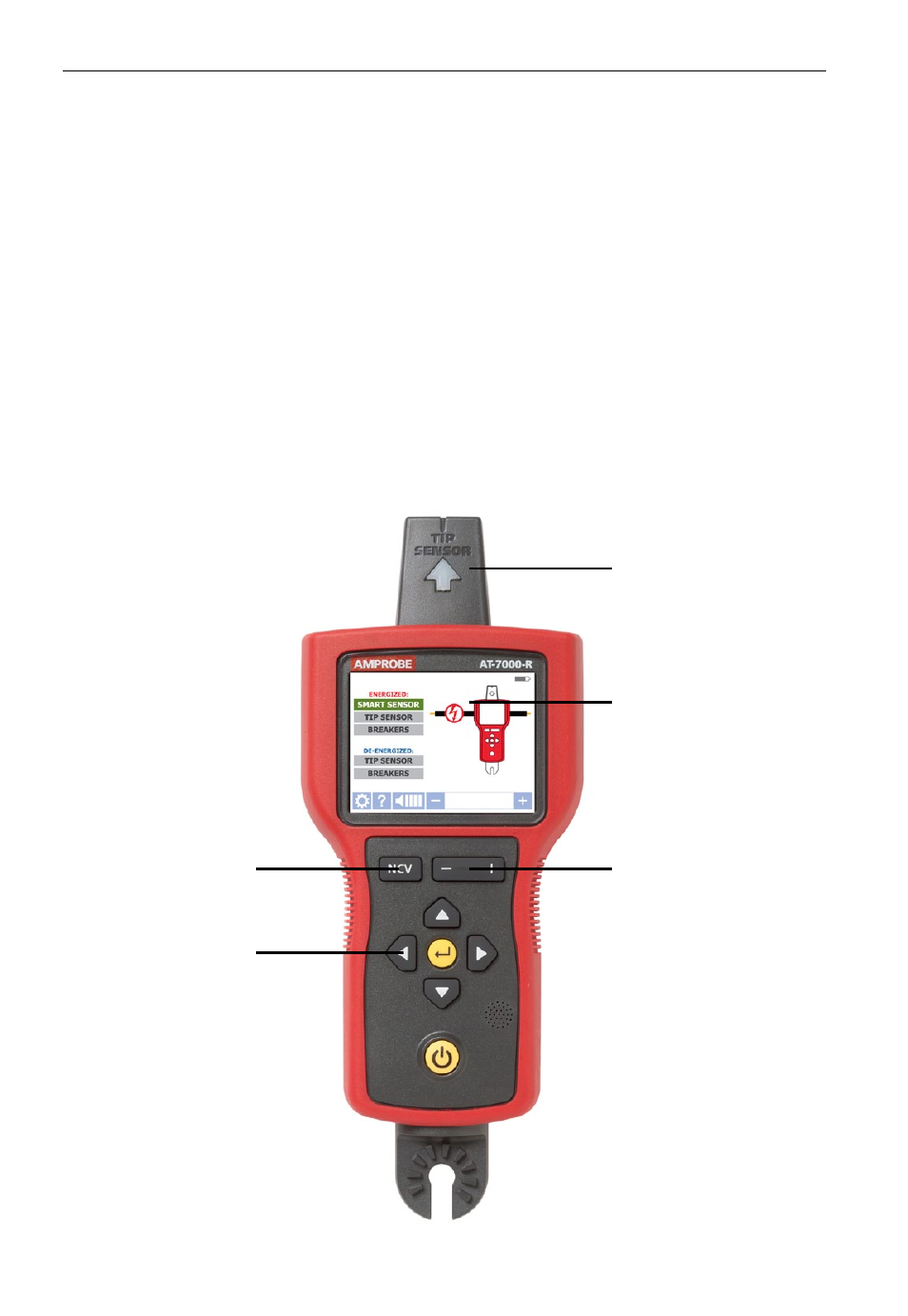
2.1 AT-7000-R Receiver
The AT-7000-R Receiver detects the signal generated by the AT-7000-T transmitter along wires
using either the TIP SENSOR or SMART SENSOR and displays this information on the full color TFT
LCD display.
Active tracing using a signal generated by the AT-7000-T Transmitter
The SMART SENSOR works with a 6 kHz signal generated along energized wires (above 30V
AC/DC) and provides an indication of the wire position and direction relative to the receiver.
The SMART SENSOR is not designed to work on de-energized systems; for that application
the TIP SENSOR should be used in de-energized mode.
The TIP SENSOR may be used on either energized or de-energized wires and can be used for
general tracing, tracing in tight spaces, locating breakers, pinpointing wires in bundles or in
junction boxes. The TIP SENSOR mode will pinpoint the wire location with both an audible
and visual indication of detected signal strength, but unlike SMART SENSOR mode it will not
provide wire direction or orientation.
Note: The receiver will NOT detect signals from the wire through metal conduit or shielded
cable. Refer to Special Applications, section 4.4 “Tracing Wires In Metal Conduit” for
alternative tracing methods.
TIP SENSOR
LCD DISPLAY
Full color TFT display
SENSITIVITY ADJUSTMENT
BUTTON (-/+)
SMART SENSOR
(Back side)
NCV BUTTON
Non-Contact
Voltage mode
4-WAY
NAVIGATION KEYS
RUBBER OVER
MOLDED ENCLOSURE
ENTER BUTTON
Selects the functions
POWER BUTTON
Turns unit On / Off
BATTERY COMPARTMENT
(Back side)
HOT STICK ATTACHMENT POINT
Figure 1: Overview of AT-7000-R Receiver