Kit components – Amprobe AT-7000 User Manual
Page 12
8
2.2 AT-7000-T Transmitter
The AT-7000-T Transmitter works on energized and de-energized circuits up to 600V AC/DC
in Category I-IV electrical environments.
The transmitter will measure the line voltage and display it on the transmitter’s color
TFT LCD display screen. Based on detected voltage it will automatically switch to either
energized mode (30 to 600V AC/DC) or de-energized mode (0 to 30V AC/DC). The energized
mode uses a lower transmission frequency (6kHz) than de-energized mode (33 kHz) to
reduce signal coupling with nearby metallic objects and improve results. If the circuit is
energized the red LED in the upper left corner of the AT-7000-T transmitter will light.
IMPORTANT! Note that the red LED light will turn on when connected to an energized
circuit. Select the correct energized or de-energized mode on the AT-7000-R receiver when
choosing your tracing mode.
Energized mode: In energized mode the transmitter draws very low current from the
energized circuit and generates a 6.25 kHz signal. This is very important feature of the
AT-7000-T, since drawing current does not inject any signal that would harm sensitive
equipment connected to the circuit. The signal is also generated in a direct path between
the transmitter and the power source, thus NOT placing a signal onto any branches enabling
wiring tracing directly back to the breaker panel. Please note that due to this feature, the
transmitter has to be connected on the load side of the circuit.
De-energized mode: In de-energized mode the transmitter injects a 32.8 kHz signal onto the
circuit. In this mode, since the signal is injected, it will travel through all the circuit branches.
It is a high frequency, very low energy signal that will not harm any sensitive equipment
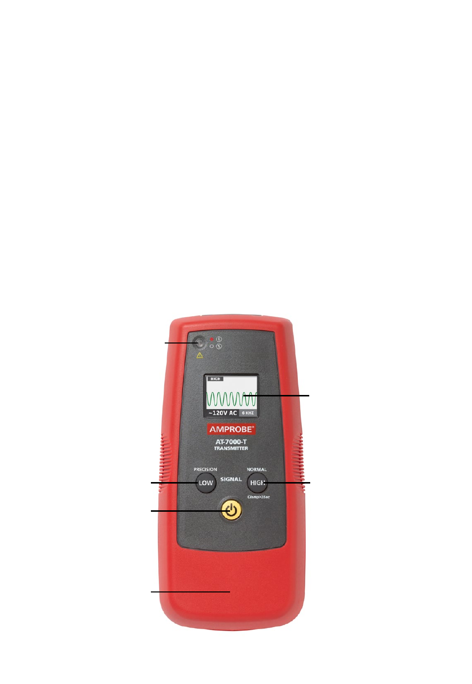
RED LED VOLTAGE INDICATOR
Indicates the transmitter mode
1. Red: Energized circuit mode
2. Amber: Overload
3. OFF: De-energized circuit
mode
LOW/PRECISION MODE
For precision applications
ON / OFF BUTTON
COLOR TFT LCD DISPLAY
TEST LEADS CONNECTION JACKS
HIGH/NORMAL MODE
Used for most applications
BATTERY COMPARTMENT
(Back side)
RUBBER OVERMOLDED
ENCLOSURE
Figure 2: Overview of AT-7000-T Transmitter
2. Kit comPonents