Special applications – Amprobe AT-7000 User Manual
Page 31
27
Figure 4.10b
Figure 4.10c
7. PRESS ENTER when complete to return to home screen.
*Note: For best results, keep the receiver at least 3 feet from the transmitter and its test
leads to minimize signal interference and improve wire tracing results.
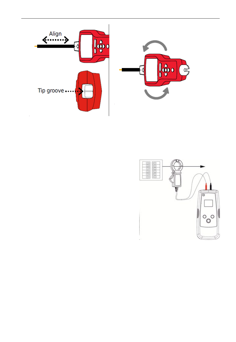
4.11 Locating Loads (Signal Clamp)
The clamp accessory can be used to map loads to
specific breakers on both energized and
de-energized systems. There is no need to
disconnect power.
1. Clamp the SC-7000 around the wire at the
breaker panel.
2. Set up the transmitter and receiver as described
in the previous section 4.10 “No Access to Bare
Conductors (Inductive Clamp)’.
3. Scan face plates of receptacles and wires
connecting loads with the TIP Sensor of the
AT-7000-R. If using on a de-energized system
you must set the receiver to de-energized TIP
SENSOR mode.
4. All the wires, receptacles and loads that have a
strong signal as indicated by the AT-70000-R are
connected to the breaker.
4. sPeciaL aPPLications