3 product application, 1 connecting end node or switch, Figure 3-3: end node or switch connection – PLANET GSD-804P User Manual
Page 13
13
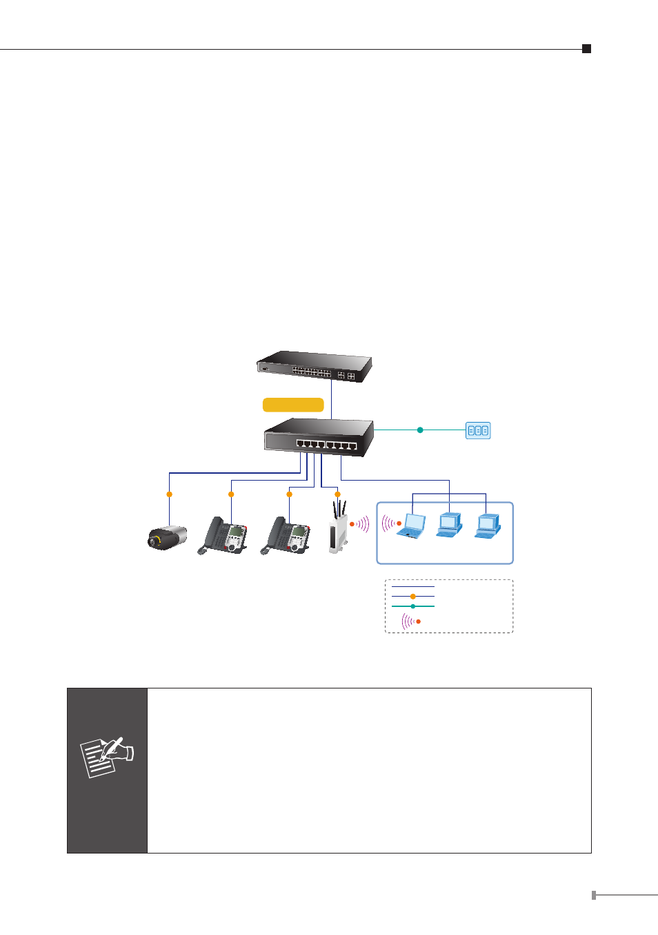
3.3 Product Application
3.3.1 Connecting end node or Switch
1. Place the GSD-804P on a smooth surface or fasten the mounting brackets
purchased separately with the provided screws in a standard 19” rack.
2. Connect the power cord to the power inlet socket of GSD-804P and the other
end into the local power source outlet. When the Switch receives power, the
Power LED should remain solid Green.
3. Connect other switch or PC to one port of the GSD-804P using Category
3/4/5/5e/6 UTP/STP cabling.
4. Connect another switch or PC to the other port of GSD-804P by following the
same process as described in Step 3.
LAN / PCs
802.3af PoE
IP Camera
802.3af PoE
VoIP Phone
N
N
PoE
PoE
PoE
PoE
Power
AC
Power Line (AC)
AC
1000Base-T UTP
PoE
1000Base-T UTP with PoE
2.4GHz 802.11n
N
GSD-804P
802.3af PoE
VoIP Phone
802.3af PoE
Wireless AP
10/100/1000Base-T Data
Figure 3-3: End node or Switch Connection
Note
Cable distance for Switch
The cable distance between the GSD-804P and PC should not
exceed 100 meter for UTP/STP cable.
Make sure the wiring is correct
It can be used Category 3/4/5 cable in 10Mbps operation. To reli-
ably operate your network at 100Mbps or 1000Mbps, you must use
an Unshielded Twisted-Pair (UTP) Category 5/5e/6 cable, or better
Data Grade cabling. While a Category 3 or 4 cables may initially
seem to work, it will soon cause data loss.