Introduction, Physical description and installation, 1 before installation – PLANET IVS-2120 User Manual
Page 8: 2 system requirements, 1 package contents, Power / do, Front panel of the ivs-2120
- 1 -
- 2 -
- 3 -
- 4 -
- 5 -
- 6 -
- 7 -
- 8 -
1. Introduction
Thank you for purchasing PLANET IVS-2120 One-channel
Industrial Internet. The IVS-2120 offers the highly-
efficient H.264 video compression, which drastically
reduces bandwidth and storage requirements without
compromising image quality. It provides an easy and
high-quality solution for integrating small or large
numbers of analog CCTV cameras into an IP-based video
surveillance system. The IVS-2120 is the ideal choice
for casinos, airports, traffic surveillance and prisons
— anywhere an analog surveillance system is already
installed and full frame rate is needed.
1.1 Before Installation
Before installation, please be sure to read this quick
installation guide and user’s manual (CD) carefully to
complete machine installation. This guide shows how to
quickly set up the IVS-2120.
1.2 System Requirements
Network
Interface
10/100Base-TX Ethernet
Monitoring
System
Recommended for Internet Explorer 8.0 or later
System
Hardware
CPU: Intel® Core™ i3 Processor or faster
Memory Size : 2GB or more
VGA card resolution : 1920 x 1080 or higher
VGA card memory : 1GB or above
This IVS-2120 provides dual power source for
redundancy. The IVS-2120’s built-in bridge rectifier
output varies accordingly so that the polarity can be
ignored. Just pay attention to its power range only.
Power / DO
Name Number Alias
Function
V1-
1
PWR1 Power1 input -- Input range is DC
12V~48V and AC 24V.
V1+
2
DO-
3
Fault
When both PWR1 and PWR2
are connected or whenever an
event occurs, the fault LED is
still off. Only when both PWR1
and PWR2 are connected will DO
be in the open circuit. Whenever
an event like motion detection is
triggered, DO will be in the closed
circuit. If either PWR1 or PWR2 is
connected, DO will be in the closed
circuit.
DO+
4
V2-
5
PWR2 Power2 input -- Input range is DC
12V~48V and AC 24V.
V2+
6
Note
1. User can see the LED power status on the
front panel to know which power source is
being connected to the IVS-2120.
2. Please note DC input power must not go
over the range. Otherwise, the product
may be damaged.
DI / RS-485
The IVS-2120 provides a general I/O terminal
block with one digital input and one output
for device control. It has 4 pins that from left
to right there are DI+, DI-, D+ terminal of
RS-485 and D- terminal of RS-485.
DI
RS485
+
-
+
-
1
2
3
4
Name Numer
Function
DI+
1
Digital signal input with
positive voltage
DI-
2
Digital signal input with
negative voltage
485+
3
RS485 data +
485-
4
RS485 data -
Note
The input voltage range of
DI+ is DC 13~30V; maximum
current is DC 8mA.
Reset
This button is hidden in the pinhole. This
button is used to restore to all the factory
default settings. Sometimes restarting the
IVS-2120 will make the system back to a
normal state. If the system still got problems
after restart, user can restore to the factory
default settings and install it again. To restore
the device, please follow the steps below:
a. Insert the paper clip or any proper tool,
and press and hold the button down
continuously.
b. Hold it at least for 5 seconds and release
the tool to get the device restored to the
default settings and reboot again.
Note
Restoring to the factory de-
fault setting will lose all the
previous settings including IP
address forever. User needs
to run the PLANET IP Wizard
II program to search the de-
vice and configure it to let the
device work properly again.
100FX
When SFP transceiver connects to SFP
receiver, the LINK/ACT LED will light on.
10/100TX
(PoE)
When RJ-45 cable connects to switch or PC,
the LINK/ACT LED will light on. If network
speed is 100Mbps, the LED will also light on.
2. Physical Description and Installation
2.1 Package Contents
IVS-2120 Unit x 1
User’s Manual CD-ROM x 1
Quick Installation Guide x 1
A/V Cable x 1
Wall Package x 1
Note
1. If any of the above items are missing,
please contact your dealer immediately.
2. Although the IVS-2120 supports AC or DC
power source, its power input range must
be noted.
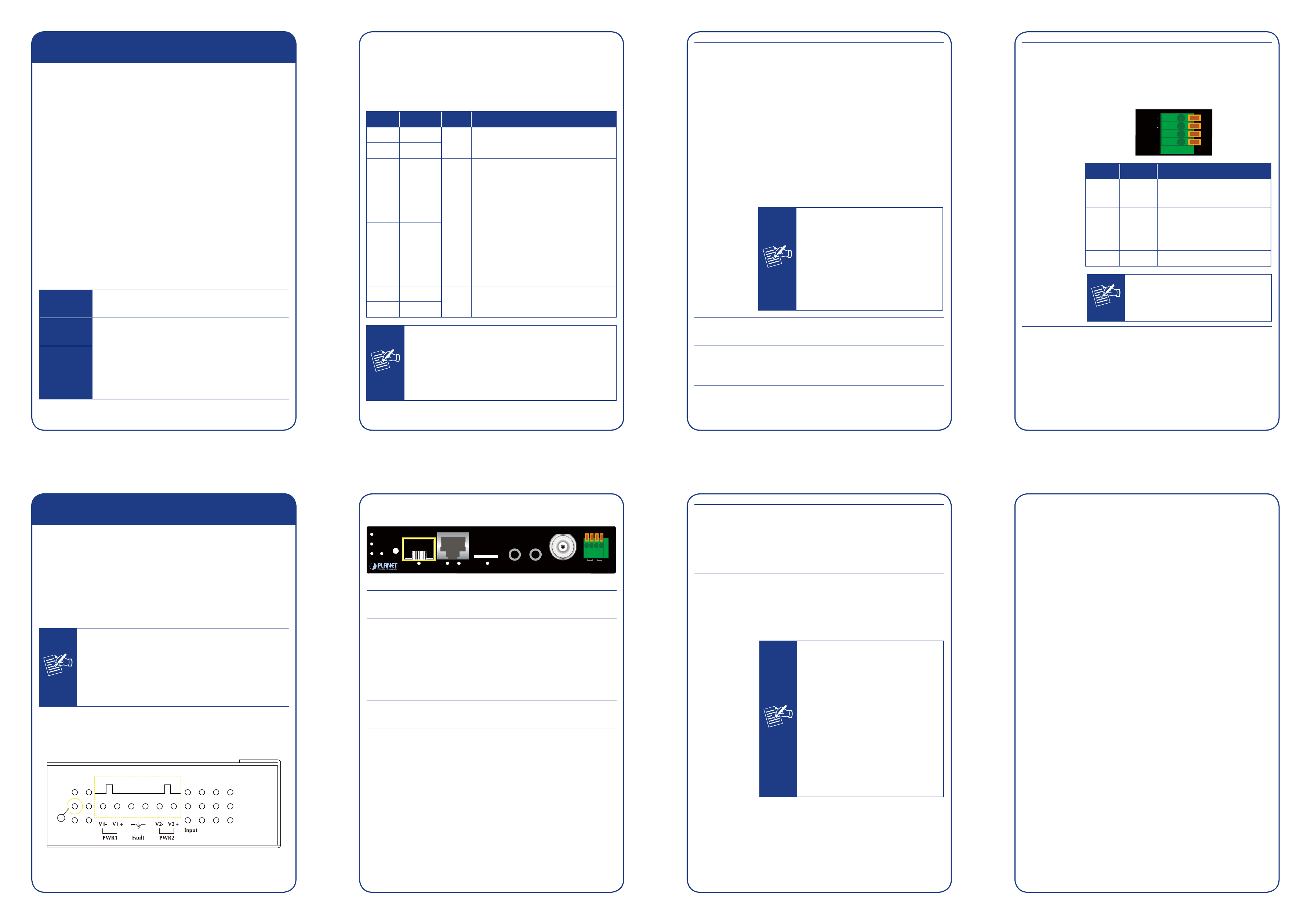
2.2 IVS-2120 Physical Details
Left-hand Side of the IVS-2120 Panel
DC12~48V, AC 24V
1 2 3 4 5 6
Front Panel of the IVS-2120
IVS-2120
Reset
PWR
100
FAL
P1
P2
VIDEO
IN
A/V O
UT
MIC IN
LNK/ ACT
LNK/ ACT
100FX
10/100TX
(PoE)
SD
1
2
DI
RS485
+
-
+
-
PWR
This LED will always light on when the
IVS-2120 is turned on.
FAL
If either Power1 (P1) or Power2 (P2) is
connected, the FAL LED will light on.
For the FAL LED to light off, both P1 and P2
need to connect to power source.
P1
When Power1 connects to power source, the
LED will light on.
P2
When Power2 connects to power source, the
LED will light on.
2.3 IVS-2120 Installation
1. Attach video source to the IVS-2120
To use the IVS-2120, user must supply video source
to the IVS-2120. Connect the BNC terminal of the
camera to the IVS-2120 video input and make sure
to power on the camera first.
2. Attach audio source to the IVS-2120 (optional)
If user needs both video and audio streams, then the
audio source should be attached to the IVS-2120.
Connect the audio device’s line output to the
IVS-2120’s Mic-in and make sure to power on your
camera or audio device first.
3. Plugging Ethernet cable into RJ-45 connector
Connect an Ethernet cable to the LAN socket located
on the IVS-2120 panel and attach it to the network.
4. Plugging SFP module into 100FX slot (optional)
Use fiber cable to connect to another SFP module.
Please note that fiber cable needs cross connection to
another SFP module.
5. Connecting RS-485 D+ and D- (optional)
When user likes a camera with P/T/Z function, they
usually need to connect their communication port
(for camera control) through RS-485. After RS-485 is
correctly connected to D+ and D-, the remote users
can control the camera movement through Internet.
6. Connect power source to PWR1 or PWR2 via terminal
block. The IVS-2120 also obtains power from PoE
switch over RJ-45 cable.
7. Done.
SD
When micro SD card is inserted into the slot
and the IVS-2120 is writing data to micro SD
card, the SD LED will light on.
Mic in
Connect an external microphone to the
IVS-2120.
A/V Out
Audio/Video-out jack allows this device
to output audio and video signal. Use the
attached A/V cable to connect A/V device
where white cable is for audio and yellow
cable is for video.
Note
1. The white jack is used for
audio output, and yellow
jack is used for video out-
put.
2. The IVS-2120 could deter-
mine whether the monitor
uses NTSC or PAL format
signal, and output the fitting
video format to monitor au-
tomatically. Please connect
the video jack (yellow) with
the monitor properly before
powering on the machine.