Data bit-order for data interface – Altera GPIO User Manual
Page 11
Signal Name
Direction
Description
oe[OE_SIZE - 1 : 0]
Input
OE connection from the core to the Altera GPIO
IP core when in bidirectional mode or in output
mode if you enable the use output enable port
parameter. OE is active high.
Set this signal to '1' when transmitting data and set
this signal to '0' when receiving data. This interface
is not present in input mode.
OE_SIZE
has different values depending on
whether the Altera GPIO configuration:
• Combinational or packed register—
DATA_SIZE
=
SIZE
• DDIO, no half-rate logic—
DATA_SIZE
=
SIZE
• DDIO with half-rate logic—
DATA_SIZE
= 2 x
SIZE
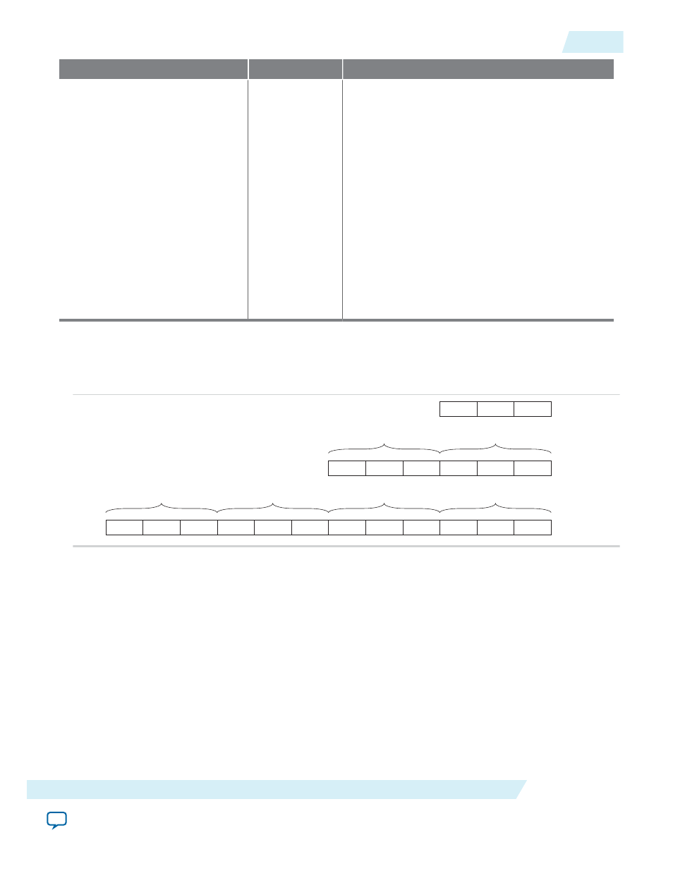
Data Bit-Order for Data Interface
The
din
,
dout
and
oe
data signals follow the following bit-order convention.
Figure 7: Data Bit-Order
SIZE - 1
...
0
t3
SIZE - 1
...
0
t2
SIZE - 1
...
0
t1
SIZE - 1
...
0
t0
4 x SIZE
SIZE - 1
...
0
t1
SIZE - 1
...
0
t0
2 x SIZE
SIZE - 1
...
0
SIZE
Where:
• If the data bus has the size value of
SIZE
, the LSB is at the right-most position.
• If the data bus has the size value of 2 x
SIZE
, it will be made of 2 words of
SIZE
.
• If the data bus has the size value of 4 x
SIZE
, it will be made of 4 words of
SIZE
.
• The LSB is in the right-most position for each word.
• The right-most word specifies the first word going out for output buses and the first word coming in
for input buses.
Note: Refer to
.
ug-altera_gpio
2014.08.18
Data Bit-Order for Data Interface
11
Altera GPIO IP Core User Guide
Altera Corporation