Input/output connections, Introduction – Optoma W350 User Manual
Page 9
9
English
Introduction
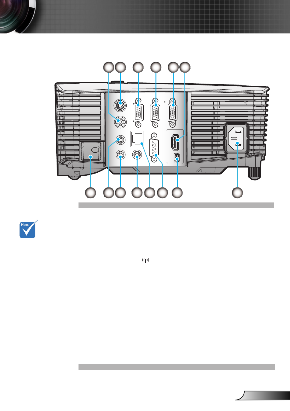
Input/Output Connections
Composite Video Input Connector
1.
S-Video Input Connector
2.
VGA-Out Connector (Monitor Loop-through Output)
3.
VGA2-IN/YPbPr Connector
4.
(PC Analog Signal/Component Video Input/HDTV/YPbPr)
VGA1-IN/YPbPr/
5.
Connector
(PC Analog Signal/Component Video Input/HDTV/YPbPr/
Wireless function via VGA Dongle)
HDMI Connector
6.
Security Lock Slot
7.
Audio2 Input
8.
Connector (3.5mm mini jack)
Audio Output Connector (3.5mm mini jack)
9.
Audio1 Input Connector (3.5mm mini jack)
10.
RS-232 Connector (9-pin)
11.
USB service and remote mouse
12.
Power
13.
RJ45
14.
Monitor loop
through only sup-
port in VGA2-IN/
YPbPr.
(*) The interface
is subject to
model’s specifica-
tions.
VGA dongle is a
optional accesso-
ry. Please contact
Optoma service
for details.
HDMI
USB
RS-232C
AUDIO1-IN
AUDIO2-IN
VIDEO
VGA-OUT
VGA2-IN/YPbPr
S-VIDEO
AUDIO-OUT
VGA1-IN/YPbPr/
RJ-45
7
9
10
12
13
8
2
3
4
5
1
6
11
14